Selecting the right high-speed transceiver technology is critical for modern network design, particularly in data centers, AI clusters, and edge computing environments. Engineers need to consider reach, channel impairments, system constraints, and form factor compatibility to ensure reliable performance at the desired bandwidth. This article delivers a framework for integrating optical link budgets, electrical compliance, and signal impairments into the decision-making process. We also explore trade-offs among FEC, modulation, and BER targets, and how to map applications to the most suitable transceivers. Finally, we extend the discussion to include market and sustainability considerations, ensuring detailed insight into both technical and strategic aspects. Whether you’re tackling intra-rack connectivity or planning for metro links, this guide equips you with actionable tools to align technology, budget, and performance for your project.
Calculating Optical Reach: Link Budgets, Dispersion Penalties, and Real-World Fit

Optical reach is never just a distance printed on a module label. It is the result of a budget calculation that asks whether transmitted signal quality, receiver sensitivity, channel loss, and impairment penalties still leave usable margin at the required error rate. For intensity-modulated direct-detect links, that usually starts with an OMA-based budget. In simple form, the available budget is the transmitter’s minimum OMAouter minus the receiver’s required sensitivity, then reduced by implementation penalties such as transmitter eye closure, receiver penalties, temperature drift, aging, and design margin. What remains must be greater than total path loss and impairment penalties.
That path loss is often smaller than engineers expect. On short single-mode links near 1310 nm, fiber attenuation may be only about 0.3 dB/km. Over 500 m, that is roughly 0.15 dB. In practice, connectors, patch panels, fanouts, and contamination often matter more than bare fiber. Two connector pairs can easily consume around 1 dB, which is why field cleanliness and realistic per-event assumptions are essential. A reach calculation that uses typical connector loss but ignores worst-case contamination can look generous on paper and fail in deployment. This is also where media choice matters; if you are still deciding between fiber types for a short or mid-range design, this guide to single-mode vs. multimode fiber selection is a useful companion.
Dispersion modeling then determines whether low attenuation actually translates into usable reach. At 1310 nm on single-mode fiber, chromatic dispersion is near its zero point, so links up to about 2 km often see only modest dispersion penalty. That is why FR-class links are practical with relatively tight power budgets. At longer distances, or near 1550 nm, dispersion grows and the source characteristics start to matter more. Spectral width, chirp, and extinction ratio all affect eye closure at the receiver. Penalty terms such as transmitter dispersion eye closure are useful because they turn these waveform effects into budgetable dB values.
A practical calculation therefore looks like this: compute channel loss from fiber length, connectors, and splices; add dispersion and PMD penalty allocations; then compare the sum against the available optical budget after subtracting implementation margin. If the remaining headroom is less than about 1 dB, the link is technically possible but operationally fragile. If margin reaches 1 to 3 dB, the design is usually healthier under temperature swing, manufacturing spread, and aging.
This is also the point where application fit becomes clearer. A 500 m or 2 km single-mode link may both pass basic math, yet the preferred choice depends on connector count, maintenance quality, thermal envelope, and tolerance for FEC overhead. Reach is therefore not just maximum distance. It is the maximum distance that still preserves dependable system margin.
Calculating Reach and Application Fit Through Copper, Twinax, and Backplane Channel Compliance
After the optical budget is understood, the same reach question must be answered for electrical channels, but with different math. Copper, twinax, and backplane links are not usually limited by simple transmit-to-receive power loss. They are limited by a combined signal integrity problem: insertion loss, reflections, crosstalk, noise, jitter, and equalization limits. In practice, reach becomes the maximum channel length or loss that still leaves enough eye opening at the slicer, usually verified through COM or related compliance methods.
For this reason, electrical reach should be expressed less as meters alone and more as a channel budget. A passive twinax cable may be physically longer, yet still fail if connector quality, host package loss, or return loss is poor. A shorter backplane path can also fail if vias and connectors create strong reflections. The calculation starts by defining the lane rate, modulation, and compliance target. For modern PAM4 channels, that usually means collecting the full S-parameter model for packages, PCB traces, cages, connectors, and cables, then evaluating insertion loss at Nyquist, effective return loss, and crosstalk from realistic aggressors.
The key metric in many Ethernet electrical clauses is Channel Operating Margin. COM converts the full channel response into a statistical margin figure after allowed transmitter and receiver equalization are applied. If the result clears the required threshold, often around 3 dB depending on the clause, the channel has enough room for the target pre-FEC BER. If COM is marginal, longer reach is not truly available even if a cable vendor lists that length as typical. This is why channel compliance is central to application fit: it tells you whether a given host, board layout, and cable assembly can actually support the intended deployment.
That decision quickly affects media choice. For intra-rack links, passive DAC is usually the best fit when reach is only a few meters and latency and power matter most. At 100G-per-lane PAM4, practical passive reach is often around 1 to 3 meters, with heavier gauge cable extending farther in favorable hosts. When the modeled channel drops below compliance, an active electrical cable or retimed break can restore margin, but adds power, cost, and some latency. For chassis and backplane paths, the same logic applies: if insertion loss and reflections push the channel beyond MR or LR class assumptions, segmentation or a different medium becomes the better engineering answer.
This is also where system design choices intersect with architecture. A denser topology may shorten copper paths enough to avoid active components, which can materially improve efficiency in latency-sensitive environments such as low-latency AI interconnect design. The important discipline is to treat copper reach as a compliance and margin problem, not a catalog-length problem, because the next step is determining how much BER headroom FEC must recover and whether that trade-off is acceptable.
How FEC, BER Targets, and Modulation Choices Shape Reach Calculations
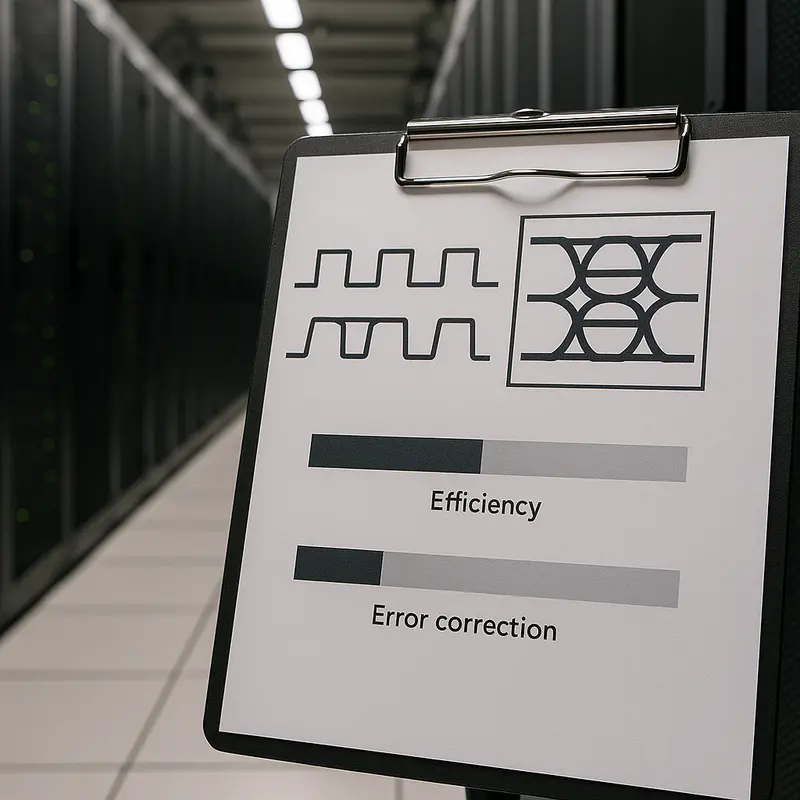
The transition from channel compliance to actual reach depends on one question: how many errors can the link tolerate before it fails the application? That is why BER targets, FEC behavior, and modulation format must be treated as one combined design problem. A raw channel that looks acceptable at first glance may still miss its reach target if its pre-FEC BER sits outside the correction range of the selected code. Conversely, a marginal optical or electrical path can become deployable when the modulation, equalization, and FEC scheme are aligned.
For modern high-speed Ethernet, this is especially important with PAM4. Compared with NRZ, PAM4 carries twice the bits per symbol, but it compresses vertical eye openings and increases sensitivity to noise, linearity limits, and jitter. In practical terms, PAM4 imposes an eye-opening penalty of roughly 9.5 dB relative to NRZ at the same symbol rate. That penalty is the reason modern PAM4 links are designed around mandatory FEC rather than around raw BER alone. A common design target is a pre-FEC BER in the 10^-4 to 10^-5 range, while the delivered service target after correction is often 10^-12 or better.
This distinction matters when calculating reach. In an optical IM-DD link, the available OMA budget is not evaluated against fiber loss alone. It is evaluated against the BER level that the receiver must meet before FEC acts, plus penalties from transmitter quality, receiver implementation, dispersion, aging, and temperature. In a copper or backplane channel, the same logic appears through COM and slicer margin. If the resulting error rate rises too close to the FEC limit, the link may pass in the lab but fail in production because normal variation pushes it into an error floor.
FEC therefore acts as a margin-conversion tool. It turns several dB of coding gain into additional tolerance for attenuation, crosstalk, or transmitter impairments. That can extend passive copper reach by a meter or two, make a 500 m PAM4 optical target realistic, or allow denser electrical packaging. But FEC is not free. It adds latency, power draw, and implementation complexity. In low-latency fabrics, that trade-off can shift the technology choice toward shorter electrical channels, cleaner optics, or architectures optimized for low-latency AI interconnect.
Modulation choice completes the picture. NRZ remains attractive where simplicity, lower raw error rates, and modest reach are enough. PAM4 improves density and lane efficiency but demands tighter BER control and stronger FEC assumptions. Coherent modulation pushes much farther, yet replaces simple power budgeting with OSNR and nonlinear analysis. So when calculating reach and application fit, modulation is never just a speed decision. It determines the BER target, the FEC dependency, the margin structure, and ultimately whether a transceiver is merely compliant on paper or truly suitable in the field.
From Reach Budget to Real-World Choice: A Practical Framework for Matching High-Speed Transceivers to the Right Application

A reach calculation is only useful if it leads to the right deployment choice. That is where application fit matters. Two links can both pass a lab budget, yet one may still be the wrong answer once power, latency, cable plant, serviceability, and upgrade path are included. The goal is not to find a transceiver that merely works. The goal is to find the lowest-risk option that meets the channel with enough margin and the fewest operational compromises.
The decision usually starts with distance, but distance alone is misleading. A three-meter link inside a rack often favors passive copper because cost, power, and latency stay low. As lane rates rise, however, host signal integrity can become the real constraint. If COM margin is thin or connector quality is inconsistent, an active electrical cable or optical link may be the better fit even at short range. For low-latency clusters, that trade-off becomes sharper because every retimer or heavy FEC stage adds delay. This is why architects often weigh physical reach and latency together rather than separately, especially in AI fabrics and tightly coupled compute environments, as discussed in low-latency AI interconnect design.
Once links move beyond the rack, media choice becomes more structural. For row or leaf–spine connections, multimode can work if an existing plant is already in place and distances remain modest. For new builds, single-mode often offers a cleaner scaling path because it avoids the tighter reach limits of modal bandwidth and aligns better with future speed upgrades. At campus distances, short-wavelength assumptions no longer protect the budget as much. Connector count, patch panels, and maintenance quality begin to matter almost as much as fiber attenuation. That is why FR-class optics often land in a practical sweet spot: enough reach for building-scale links without the cost and dispersion sensitivity of longer-reach designs.
A good decision framework therefore asks four questions in sequence. First, what is the worst-case channel, not the average one? Second, how much real margin remains after temperature, aging, contamination, and manufacturing spread? Third, what is the system penalty for making the link longer through DSP, retimers, or stronger optics? Fourth, does the choice still make sense when multiplied across every port in the fabric?
This approach prevents a common mistake: selecting by headline reach alone. A longer-rated module is not automatically better if it raises power, thermal load, or cost without solving the actual constraint. In some designs, reducing connector events creates more usable margin than moving to a higher-reach optic. In others, changing from copper to fiber simplifies airflow and future upgrades. Application fit, then, is the discipline of translating calculated reach into an architecture decision that remains technically sound, economically reasonable, and operationally sustainable.
Beyond the Link Budget: Economic, Supply-Chain, and Sustainability Factors in Transceiver Reach Decisions

A reach calculation is only complete when it answers a business question, not just a physics question. Two options may both close the budget, meet BER targets, and pass margin requirements, yet differ sharply in total cost, deployment risk, and long-term efficiency. That is why application fit must extend beyond optical loss, COM, or OSNR. It must also account for what the organization can buy, power, cool, maintain, and replace over the life of the network.
The first filter is usually economics. Short electrical links remain attractive because they minimize acquisition cost and often reduce power draw. Passive copper is especially compelling when the calculated reach stays inside a few meters and host signal integrity is strong. Once channels become longer or less forgiving, active electrical or optical options may become cheaper in system terms, even if their unit price is higher. A lower-cost cable that forces retimers, larger thermal headroom, or repeated troubleshooting can erase its apparent savings. This is why cost per transported bit should be evaluated alongside port power, expected failure handling, and installation labor. Designers comparing architectures often find that medium choice affects more than optics pricing alone; it also changes rack airflow, cabling density, and upgrade flexibility. That trade-off becomes even clearer when planning fabrics such as leaf-spine, where media selection shapes scaling efficiency and serviceability, as discussed in best optical architecture for leaf-spine.
Supply-chain resilience is the second filter. A technically ideal module is not a good fit if lead times are unpredictable or component sourcing is concentrated in a fragile region. High-speed transceivers depend on lasers, DSPs, advanced packaging, substrates, and precision connectors. Any disruption can change availability, substitution rules, or qualification timelines. Standards-based interoperability reduces lock-in, but it does not remove exposure to export controls, certification barriers, or shifts in regional manufacturing capacity. In practical reach planning, this means favoring designs with some sourcing flexibility and enough margin to tolerate alternate vendors without reworking the full channel design.
Sustainability adds a third layer, and it should be treated quantitatively. Higher-reach technologies usually consume more power per port because they need stronger optics, heavier DSP, or more complex FEC. Over thousands of links, a small per-port increase becomes a meaningful operating cost and cooling burden. The most sustainable choice is rarely the most advanced option; it is the lowest-power technology that still preserves margin. If a passive or short-reach optical solution satisfies distance, BER, and latency constraints, moving to a more power-hungry design offers little environmental benefit. Conversely, slimmer fiber can improve airflow and reduce cable bulk, which may lower cooling demand indirectly. So when calculating reach and application fit, the final margin review should include watts, replacement risk, and operational waste alongside decibels.
Final thoughts
Accurately calculating reach and selecting the right high-speed transceiver involves balancing performance, cost, and constraints. By leveraging optical link budgets, electrical compliance metrics, and a robust application-fit framework, you can ensure your network is equipped to meet both current requirements and future scalability. Additionally, understanding the broader economic and sustainability impacts of your decisions can position your infrastructure for long-term efficiency and resilience. The insights and methodologies shared here aim to guide you in making informed and effective choices.
Talk to ABPTEL about high-speed optics, MTP/MPO cabling, and data center interconnect solutions.
Learn more: https://abptel.com/contact/
About us
ABPTEL provides high-speed optical transceivers, MTP/MPO cabling systems, DAC and AOC cables, PoE switches, FTTA solutions, and fiber tools for data center, AI, telecom, and network infrastructure projects.
Talk to ABPTEL
Looking for the right optical hardware for your AI data center, GPU cluster, or FTTA project? ABPTEL ships from Shenzhen with OEM/ODM support, fast lead times, and engineering-level pre-sales advice.
- 🔥 400G & 800G OSFP / QSFP-DD Transceivers — for AI training fabrics and hyperscale spine-leaf
- 📡 MPO / MTP High-Density Cabling — 12 / 24 / 32-fiber for high-density data centers
- ⚡ AOC & DAC Cables — short-reach GPU interconnects, OEM compatible
- 🧩 SFP / SFP+ / SFP28 / QSFP28 Modules — 1G to 100G optical transceivers
- 📋 Data Center Cabling Solutions — end-to-end design guide
- ❓ Read our FAQ — compatibility, polarity, lead time, MOQ
💬 Get a quote in 12 hours: Contact Candy · WhatsApp +86 188 1445 5697 · candy@abptel.com