When building modern data centers, metro networks, or AI infrastructure, selecting the right 400G optical modules is a critical decision. These modules tie directly into the network’s performance, reliability, and lifecycle economics. However, mistakes in choosing the right form factor, optical interface, FEC configurations, or thermal parameters can result in service disruptions, elevated costs, and stalled scalability. This guide examines the key challenges, starting with form-factor compatibility and connections, before progressing into reach considerations, electrical architecture, reliability factors, and supply chain strategies. Each chapter unveils actionable insights to help data center network engineers, AI planners, procurement managers, and integrators avoid common pitfalls while optimizing deployments.
The First 400G Selection Mistake: When Form Factor Fit Hides Host Platform Incompatibility
One of the most expensive 400G selection errors happens before fiber, reach, or optics type are even discussed: choosing a module that seems to fit the port, but does not truly fit the platform. At 400G, physical insertion is only the starting point. The host switch or router must also support the module’s electrical lane design, power class, thermal behavior, and management interface. When buyers treat these as secondary checks, deployments stall at turn-up.
The confusion usually starts with form factors that appear close in purpose but differ in practical support. QSFP-DD and OSFP both serve 400G, yet they are not interchangeable in any simple sense. They have different cages, different thermal envelopes, and often different platform assumptions. A host may accept one family but not the other, or it may support only certain power classes within that family. That matters because a 400G module that draws too much power can trigger throttling, unstable operation, or outright port shutdown. The same issue appears when teams assume that a newer electrical interface automatically works in older hardware. A host built around 8 x 50G electrical lanes will not behave like one designed for 4 x 100G lanes.
Management compatibility is another hidden failure point. Many 400G modules depend on CMIS support for proper monitoring and control. If the network operating system supports an older CMIS revision, key functions may be unavailable or unreliable. This becomes even more important with advanced modules that expose richer diagnostics, tuning controls, or coherent features. In practice, the module may be standards-based, but the host software still decides whether it behaves correctly.
Vendor coding creates a quieter version of the same mistake. A standards-compliant optic can still be rejected by the platform if EEPROM policies are restrictive. That turns procurement into an interoperability problem, not just a sourcing decision. For teams comparing options, it helps to review a broader framework for evaluating high-speed optics before locking in a transceiver list.
Mechanical details also matter more than many buyers expect. Higher-density ports leave less room for cable boots, latch access, and airflow. A module that meets the data sheet can still create trouble if the faceplate is crowded, the heat sink is wrong, or stiff patch cords block adjacent ports. Over time, these issues become reliability problems, not just installation annoyances.
The safest approach is to validate form factor, host lane architecture, CMIS version, approved power class, airflow direction, and coding policy as a single compatibility stack. If any layer is assumed rather than confirmed, the wrong 400G module can look right until the moment it has to carry traffic.
What Are the Most Common Mistakes in 400G Optical Module Selection: Choosing the Wrong Reach, Fiber, and Optical Interface for the Link
After platform compatibility is confirmed, the next costly mistake is assuming any 400G optic with the right speed will suit the link. In practice, most failures begin with a bad match between distance, fiber plant, connector type, and optical standard. A module may be standards-compliant and still be completely wrong for the installed cabling.
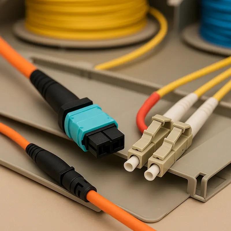
The first trap is confusing multimode and single-mode use cases. Short-reach multimode options are attractive inside dense rows, but they are tightly tied to connector format and parallel fiber counts. A common example is ordering an MPO-12 plant for a standard that actually needs MPO-16. Another is treating two multimode variants as interchangeable when their polarity and wavelength behavior differ. The same mistake appears on single-mode links. A short duplex jumper cannot replace a parallel-fiber interface, and an LC-based module cannot simply be patched into an MPO design without the correct breakout method. Teams that need a refresher on single-mode vs multimode fiber choices often avoid these expensive ordering errors.
Reach is misjudged just as often. A 500-meter interface is not a 2-kilometer interface with less margin, and a 2-kilometer optic is not a budget version of a 10-kilometer one. These standards use different optical architectures, wavelengths, and loss assumptions. Choosing a longer-reach module than necessary wastes capital and adds power draw. Choosing a shorter-reach module for a marginal span creates intermittent failures that are harder to diagnose than a hard link-down event.
The real problem is usually not headline distance. It is total channel loss. Connector loss, splice loss, patch panels, fan-outs, and fiber attenuation all consume budget. Duplex single-mode links may look simple on paper, yet several mated pairs can quickly erase margin. Parallel optics can be even less forgiving when MPO quality, polarity, or cleanliness is poor. Many teams also forget to reserve engineering margin for aging, contamination, and temperature drift. A link that passes in the lab can become unstable in production if it was designed to the absolute limit.
Optical interface standards add another layer of risk. Legacy 8-wavelength options still appear in the market, but many modern designs are built around 4x100G-lambda optics. Mixing generations can complicate interoperability, power planning, and sparing. Reflection sensitivity matters too. Endface type is not a minor detail. UPC and APC are not interchangeable, and a mismatch can raise reflectance enough to hurt PAM4 performance.
For longer data center interconnect paths, the mistake becomes even larger. Coherent 400G modules are not just longer-reach versions of direct-detect optics. They depend on a proper DWDM line system, filter plan, and optical margin. Selecting them for a simple intra-building link adds cost with no practical gain. Selecting direct-detect optics for spans that really need coherent transport creates the opposite problem: a design that never had enough margin to begin with.
What Are the Most Common Mistakes in 400G Optical Module Selection: Ignoring FEC, Lane Mapping, and Breakout Design Realities
After reach and fiber choices are settled, many 400G selection errors move up the stack and become electrical problems disguised as optical ones. A module may match the distance and connector type perfectly, yet still fail because the host expects a different lane structure, the link partners apply different FEC policies, or the breakout plan was never validated end to end. These mistakes are common because 400G optics often look simple from the faceplate, but behind that connector sit strict assumptions about how traffic is split, corrected, and presented to the switch.
The first trap is treating all 400G ports as electrically equivalent. Many 400G modules are built around 8x50G PAM4 electrical lanes, while newer designs may expect 4x100G signaling. If the switch ASIC, cage, or software supports one model and the optic expects the other, the port may not initialize at all. In some cases, a gearbox bridges that mismatch, but that adds power, cost, and a small latency penalty. Teams often budget for optics and cabling, then forget that electrical conversion inside the module is not free.
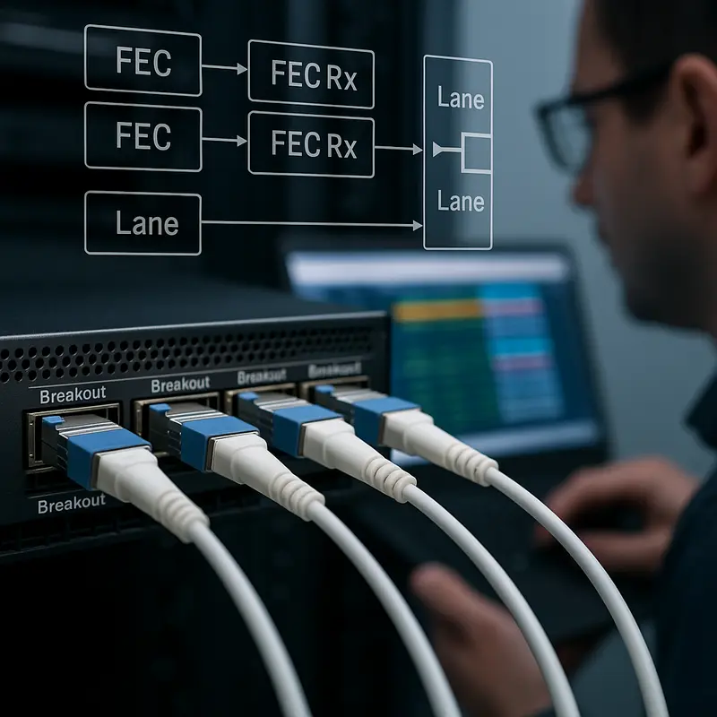
FEC is the second major blind spot. PAM4 delivers density, but it depends on strong error correction to stay usable. With 400G, RS-FEC is usually not optional in practice. A link can show acceptable raw performance only because FEC is cleaning up a relatively high pre-FEC error rate. If one side disables FEC, uses a different policy, or relies on host behavior the other side does not support, the result can be link flaps, poor margin, or silent packet loss. This is especially dangerous during mixed-vendor deployments, where standards support may exist on paper but implementation details differ. For teams comparing architectures, this is also why understanding how to evaluate high-speed optics requires looking beyond the module label.
Breakout planning creates the third class of mistakes. A 400G port does not automatically become four clean 100G ports just because the optic datasheet mentions breakout. The switch must support sub-port mapping, the operating system must expose those lanes correctly, and the far-end optics must match the breakout type. A 400G DR4 design, for example, may cleanly break into 4x100G DR1, but not into whatever 100G optics happen to be available in inventory. Even when the physical harness is correct, operational details matter. Telemetry, QoS, and port policies may need to be applied per breakout leg, not at the parent port.
The selection mistake, then, is not merely choosing the wrong optic. It is assuming the electrical lane plan, FEC behavior, and breakout architecture will somehow sort themselves out later. At 400G, they rarely do.
What Are the Most Common Mistakes in 400G Optical Module Selection: When Thermal Limits, Power Density, and Mechanical Details Undermine Reliability
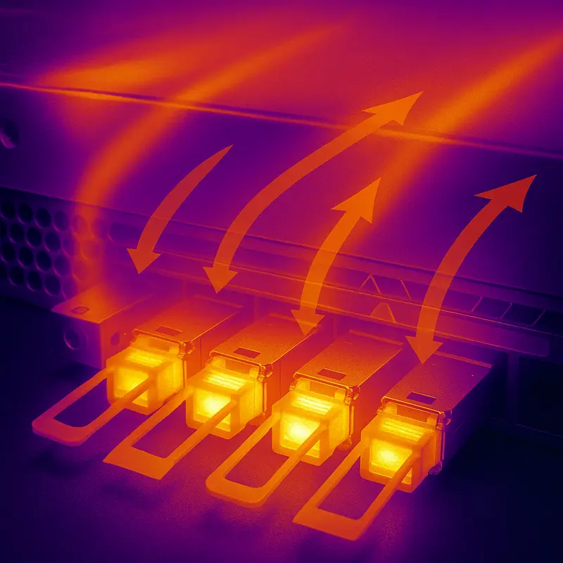
After lane mapping and breakout choices are settled, many 400G deployments still fail for a simpler reason: the module can link in the lab, but not survive in a fully populated chassis. This is where selection errors shift from protocol logic to physics. A 400G optic that looks compatible on the datasheet may exceed the port power class, overwhelm the switch airflow design, or run too close to its case temperature limit once adjacent ports are populated. Those mistakes often appear only under real traffic and ambient conditions, which makes them expensive to diagnose.
The first trap is treating module power as a minor specification. It is not. Power draw affects thermal load, rack cooling, and long-term operating cost at the same time. A few extra watts per port may seem harmless, yet at scale they raise inlet temperatures and reduce headroom across the faceplate. Higher-power coherent and long-reach modules are especially unforgiving in dense systems. If the platform airflow direction, fan capacity, heatsink design, and altitude derating are not checked together, ports may throttle, log rising error counts, or shut down intermittently. This is why module selection should be reviewed alongside broader high-speed optics evaluation criteria rather than as a standalone optics purchase.
Thermal mistakes are often compounded by mechanical ones. High-density 400G hardware leaves little room for stiff patch cords, bulky boots, or poorly planned cable exits. Tight bends near the transceiver cage can increase insertion loss and create intermittent faults that look like random optical instability. MPO terminations are particularly sensitive because strain, contamination, and poor mating geometry can all degrade performance. Repeated insertions also wear cages and latches over time, especially when technicians are forced to work in cramped faceplates. In practice, reliability depends as much on cable routing discipline and cleaning procedures as on the transceiver itself.
Another common mistake is ignoring live telemetry until a link fails. Digital diagnostics should be treated as an early warning system, not a forensic tool. Temperature, received power, transmit power, and pre-FEC indicators can reveal clogged airflow paths, dirty connectors, or a marginal optical budget well before service impact occurs. Without thresholds and monitoring, operators miss the slow drift that usually precedes failure.
The deeper lesson is that 400G module selection is never just about nominal reach or interface type. A module must fit the platform electrically, survive thermally, and integrate mechanically with the real cabling environment. If any one of those conditions is overlooked, a technically correct choice can still become an operationally fragile one.
What Are the Most Common Mistakes in 400G Optical Module Selection: Hidden Cost Traps, Supply Risks, and 800G Readiness

The last major selection error appears after the link is technically sound: teams optimize for purchase price, then absorb larger costs later. In 400G optical module selection, the cheapest part on a quote sheet is often the most expensive choice across the deployment lifecycle. A module that exceeds the required reach raises both capital and operating costs. Choosing LR4 for a 1 km link, for example, buys distance that the network never uses while adding power draw across every port. The reverse mistake is just as costly. Selecting DR4 for a span that sits near 700 to 1000 meters may look economical at first, but it can force redesigns, added patching, or emergency replacements once margin disappears.
This is why total cost of ownership matters more than unit price. Power is part of that equation. Even a small wattage increase multiplies quickly across hundreds or thousands of ports. Cabling is another hidden variable. DR4 can lower transceiver cost and support efficient 4x100G breakout designs, but MPO trunks, polarity management, cleaning discipline, and breakout harness complexity can raise operational overhead. FR4 and LR4 often cost more per module, yet LC duplex cabling is simpler to deploy and maintain. The right answer depends on labor, existing plant, and growth plans, not just optics pricing. A useful companion perspective is this guide to evaluating high-speed optics, especially when comparing long-term efficiency rather than initial spend.
Supply chain mistakes are equally common because 400G availability is not driven by one component alone. Lead times can stretch when DSPs, EML lasers, or packaging capacity tighten. If a design depends on one coded module from one approved source, a single shortage can delay an entire build. That risk grows when platforms enforce strict EEPROM coding or rely on proprietary diagnostics. Multi-vendor qualification, standards-based management support, and a defined spare policy reduce that exposure. Keeping a modest pool of spares per optic type usually costs far less than prolonged outage recovery or delayed turn-up.
Future-proofing is where many short-term decisions become long-term constraints. A deployment built only for immediate 400G needs may miss an easy path to 800G. Structured cabling based on reusable single-mode trunks, especially for DR4 or FR4 style architectures, often creates smoother migration options later. Host platforms that support 100G-per-lane electrical signaling also reduce future gearbox penalties. The mistake is not failing to predict the future perfectly. It is locking the network into a form factor, lane model, or cabling choice that makes the next upgrade unnecessarily expensive, power-hungry, or operationally fragile.
Final thoughts
Selecting the right 400G optical modules is essential for achieving the reliability, scalability, and cost-efficiency demanded by modern networks. Avoiding form factor mismatches, ensuring accurate reach and fiber compatibility, managing FEC configurations, and accounting for thermal/power needs can minimize operational risks while optimizing overall TCO. Future-proofing your choices allows seamless scalability to 800G and beyond while supporting next-generation architectures. By following best practices in alignment with modular, economic, and technical goals, you can create infrastructures capable of meeting growing traffic demands efficiently.
Talk to ABPTEL about high-speed optics, MTP/MPO cabling, and data center interconnect solutions today!
Learn more: https://abptel.com/contact/
About us
ABPTEL provides high-speed optical transceivers, MTP/MPO cabling systems, DAC and AOC cables, PoE switches, FTTA solutions, and fiber tools for data center, AI, telecom, and network infrastructure projects. With expertise in scalable architectures and reliable network performance, ABPTEL ensures your interconnect solutions are future-proof, energy-efficient, and designed to support evolving demands.
Talk to ABPTEL
Looking for the right optical hardware for your AI data center, GPU cluster, or FTTA project? ABPTEL ships from Shenzhen with OEM/ODM support, fast lead times, and engineering-level pre-sales advice.
- 🔥 400G & 800G OSFP / QSFP-DD Transceivers — for AI training fabrics and hyperscale spine-leaf
- 📡 MPO / MTP High-Density Cabling — 12 / 24 / 32-fiber for high-density data centers
- ⚡ AOC & DAC Cables — short-reach GPU interconnects, OEM compatible
- 🧩 SFP / SFP+ / SFP28 / QSFP28 Modules — 1G to 100G optical transceivers
- 📋 Data Center Cabling Solutions — end-to-end design guide
- ❓ Read our FAQ — compatibility, polarity, lead time, MOQ
💬 Get a quote in 12 hours: Contact Candy · WhatsApp +86 188 1445 5697 · candy@abptel.com