How Do You Test OPGW Cables?
I have been working in the optical communications industry for many years. I have seen many projects where the reliability of cables was crucial. I have also seen the damage that can occur when cables are not tested properly. In my work, I have learned that testing OPGW cables is a vital process. OPGW stands for Optical Ground Wire. These cables are used on high voltage power lines. They have a dual purpose. They carry optical signals and also serve as a ground wire for lightning protection. I have managed many projects where I personally oversaw the testing process. I know that if testing is ignored or done incorrectly, it can lead to failures that affect entire networks.
In this article, I will share my experience and detail the testing methods I use to ensure OPGW cables function as they should. I will explain the key methods of testing, the importance of each test, and how proper documentation supports ongoing maintenance. I will also include personal stories from field projects and use many tables and subheadings to organize the content clearly.
What Are the Key Methods for Testing OPGW Cables?
Testing OPGW cables is a multi-step process. I always start with basic visual inspection. Then, I move to optical tests using devices like the OTDR. I also perform power measurements and mechanical tests. Environmental tests are equally important. Each of these steps is necessary to ensure that the cable will work well under the stresses of real-world conditions.
Key OPGW testing methods include visual inspection, OTDR testing, optical power meter testing, continuity tests, and various mechanical and environmental tests. Each method targets a specific aspect of cable performance and safety.
To help you understand these methods better, I have organized this section into several detailed subsections. I use tables to summarize the key points for each test type.
Visual Inspection
I always start with a visual inspection. This test is the first step. I check the cable’s exterior for any visible damage. I look for cuts, abrasions, or signs of wear. I also inspect connectors and splices. This step is simple but effective.
Visual Inspection Checklist
| Checkpoint | What I Look For |
|---|---|
| Cable Sheath | Cuts, abrasions, or signs of aging |
| Connectors | Corrosion, loose connections |
| Splice Areas | Visible damage or misalignment |
| Overall Condition | Consistency in color and material integrity |
I remember a project where a small cut in the cable sheath was overlooked during the initial inspection. This minor defect later led to a major failure under heavy wind. That experience taught me never to skip a visual check.
Optical Time-Domain Reflectometer (OTDR) Testing
OTDR testing is a crucial optical method. I use an OTDR to send a pulse of light down the cable. The device measures reflections along the cable. Any breaks, bends, or splices show up as changes in the reflected signal. This non-invasive test helps me locate faults with high accuracy.
OTDR Testing Overview
| Test Aspect | Details |
|---|---|
| Test Pulse | A light pulse is sent down the fiber |
| Reflection Analysis | Faults and splices are identified from reflections |
| Fault Location | Distance to a fault can be measured accurately |
| Signal Loss | Insertion loss is measured to assess cable performance |
I have used OTDR testing on many projects. One project in a coastal area required me to map out several splices over a 10 km span. The OTDR helped me pinpoint small faults that were not visible by eye.
Optical Power Meter Testing
After OTDR testing, I always use an optical power meter. This test measures the optical power loss in the cable. I inject a known light level at one end and measure the output at the other. The difference gives the insertion loss. A high insertion loss may indicate damage or a poorly spliced joint.
Optical Power Meter Testing Procedure
| Step | Action |
|---|---|
| Light Injection | Inject a calibrated light power into the cable |
| Measurement at Receiver | Measure the optical power at the other end |
| Calculate Insertion Loss | Subtract output power from input power |
| Compare with Standards | Verify that loss is within acceptable limits |
In one of my projects, the optical power meter test revealed an unexpected 2 dB loss in a cable run. I traced the problem to a splice that was not properly fused. This test helped me prevent a potential data transmission issue.
Continuity Testing
Continuity testing is essential to check that the light travels uninterrupted through the fiber. I use a visual fault locator. This device sends a visible laser light through the fiber. Any breaks in the cable will be apparent, ensuring that the optical path is clear.
Continuity Testing Key Points
| Test Tool | Purpose |
|---|---|
| Visual Fault Locator | Identify breaks or discontinuities in the fiber |
| Laser Light Source | Confirm that light is transmitted along the cable |
| Fiber Inspection | Visual check of the entire fiber length |
During a recent installation, I discovered a minor break in the fiber using a visual fault locator. Early detection allowed me to replace the faulty segment before the network went live.
Mechanical Tests
Mechanical tests are used to evaluate the physical strength and durability of the cable. I perform several tests that mimic real-world stresses. These tests include creep tests, stress-strain tests, and breaking strength tests. They help ensure that the cable can handle tension, bending, and other physical forces.
Mechanical Testing Methods
| Test Type | Purpose | Key Outcome |
|---|---|---|
| Creep Test | Monitor long-term tension effects | Determine cable sag and stability |
| Stress-Strain Test | Measure material elasticity and strength | Calculate Modulus of Elasticity and breaking points |
| Breaking Strength Test | Verify that the cable meets its rated tensile strength | Ensure safety under maximum load conditions |
| Sheave, Crush, Bend Tests | Assess resistance to various mechanical stresses | Confirm robustness in real-world installation scenarios |
I recall performing a creep test on a long-span cable. The test data helped me adjust the sag calculations to prevent future sagging under load. This attention to mechanical detail is key to ensuring long-term cable performance.
Environmental and Performance Tests
OPGW cables face harsh environmental conditions. I conduct environmental tests to simulate these conditions. These include temperature cycle tests, water ingress tests, and salt spray tests.
Environmental Testing Overview
| Environmental Test | Description | What It Measures |
|---|---|---|
| Temperature Cycle Test | Expose cable to extreme hot and cold cycles | Thermal stability and performance under temperature stress |
| Water Ingress Test | Simulate prolonged exposure to water | Cable sealing and resistance to moisture |
| Salt Spray Test | Expose cable to saline conditions | Corrosion resistance, especially for coastal installations |
In one coastal project, water ingress tests were crucial. The results showed that a particular batch of cables needed an extra layer of water-blocking gel. These tests ensure that cables can endure their operational environment.
Why Is Documentation and Reporting Crucial in OPGW Testing?
Accurate documentation is as important as the tests themselves. I maintain detailed records of every test. I record the methods used, the results, and any anomalies. This documentation helps in future maintenance and troubleshooting.
Documentation Best Practices
| Documentation Aspect | What I Record | Importance |
|---|---|---|
| Test Methodology | Detailed procedure of each test | Ensures repeatability and standardization |
| Test Results | Quantitative data (e.g., insertion loss, strain) | Allows comparison against industry standards |
| Anomalies and Corrections | Any unexpected findings and corrective actions | Facilitates prompt resolution and continuous improvement |
I have seen how thorough documentation has saved projects. In one instance, detailed records helped me trace a recurring issue to a specific installation step. This allowed for targeted improvements that enhanced overall reliability.
Additional Testing Considerations
I always believe that deeper understanding leads to better outcomes. Below, I share extra details and tips that I have learned over the years. These sections include further analysis, tables, and examples to help you grasp the nuances of OPGW cable testing.
In-Depth Analysis of OTDR Testing
OTDR testing is one of my most relied-upon methods. I use it to get a full picture of the cable’s health. The device sends a light pulse and measures the reflection along the cable. This helps me locate splices, bends, and other discontinuities.
OTDR Data Analysis Table
| Parameter | Description | Why It Matters |
|---|---|---|
| Backscatter Level | Indicates signal return due to imperfections | Helps detect cable degradation |
| Event Loss | Signal loss at splices or connectors | Identifies problematic splice points |
| Fault Location | Distance from the test point to a fault | Enables precise repairs |
| Insertion Loss | Total loss over the cable length | Ensures overall network efficiency |
I remember a project where the OTDR data revealed a splice with 1.5 dB loss. That value was higher than acceptable, so I re-spliced the cable. The result was a successful, low-loss connection that improved overall performance.
Detailed Optical Power Meter Testing
The optical power meter test is essential to check signal strength. I inject a known light level at one end of the cable. I then measure the output at the other end. The difference between the input and output gives me the insertion loss.
Optical Power Testing Data
| Test Step | Action | Expected Result |
|---|---|---|
| Light Injection | Send a calibrated light signal into the cable | Consistent input light level |
| Measurement | Measure output power at the receiving end | Output power should be within acceptable loss limits |
| Calculation | Determine insertion loss from input and output | Insertion loss should be minimal |
This test is simple but very effective. I use it routinely to ensure that the fiber’s performance remains high. Even a small deviation can indicate a problem that needs attention.
Advanced Mechanical Testing Techniques
Mechanical testing involves several methods. I perform creep tests to measure how cables stretch over time under constant load. I also do stress-strain tests to understand the material properties of the cable. These tests help me ensure that the cable will not fail under operational stress.
Mechanical Testing Comparison Table
| Test Type | Method | Key Metric |
|---|---|---|
| Creep Test | Measure elongation under a constant load | Long-term sag and stability |
| Stress-Strain Test | Gradually increase load to measure deformation | Modulus of Elasticity, breaking point |
| Breaking Strength Test | Apply force until the cable fails | Rated Tensile Strength (RTS) |
| Bend and Crush Test | Subject cable to bending and compression forces | Resistance to mechanical damage |
I recall a test where a cable underwent a stress-strain test. The results confirmed that the cable’s modulus of elasticity was within the required range. This testing is vital to ensure that the cable will perform reliably over its service life.
Environmental Testing in Depth
Environmental tests simulate real-world conditions. I perform temperature cycle tests that expose cables to extreme hot and cold. I also do water ingress tests and salt spray tests to see how the cable handles moisture and corrosive elements.
Environmental Testing Overview
| Test Type | Description | Importance |
|---|---|---|
| Temperature Cycle Test | Alternate heating and cooling cycles | Ensures cable performance under thermal stress |
| Water Ingress Test | Submerge cable sections to check for water penetration | Verifies cable sealing and water resistance |
| Salt Spray Test | Expose cable to saline conditions | Critical for installations near coastal areas |
| Vibration Test | Simulate wind-induced vibrations | Assesses long-term durability under dynamic conditions |
I once oversaw a temperature cycle test on a batch of cables. The cables maintained performance even after repeated cycles, which reassured the project team that the cables would be reliable in harsh climates.
Why Is Thorough Documentation Essential in OPGW Testing?
I always stress the importance of detailed documentation. It records every test, observation, and measurement. This record helps in tracking performance over time and diagnosing issues quickly.
Best Practices for Documentation
In my work, I use standardized forms to record test results. I include details such as test type, equipment used, measured values, and any anomalies.
Documentation Checklist
| Item | Details to Record | Benefit |
|---|---|---|
| Test Method | Steps and procedures followed | Ensures repeatability and standardization |
| Test Results | Measured values and observations | Allows for performance comparison over time |
| Anomalies Observed | Deviations from expected results | Helps in troubleshooting and corrective action |
| Equipment Calibration | Details of calibration status of instruments | Ensures accuracy and reliability of test results |
| Date and Time | When the test was conducted | Aids in tracking historical performance |
I have often referred back to old test records to troubleshoot issues. Detailed documentation has saved many projects by providing a clear history of cable performance.
Reporting for Continuous Improvement
After testing, I compile a comprehensive report. This report includes all documentation, analysis, and recommendations. It is shared with the project team and stored for future reference.
Reporting Format Table
| Section | Content Description | Purpose |
|---|---|---|
| Executive Summary | Key findings and overall cable performance | Provides a quick overview for decision-makers |
| Detailed Test Results | Data from OTDR, power meter, mechanical, and environmental tests | Offers an in-depth look at performance metrics |
| Anomaly Analysis | Identification and analysis of any issues | Guides corrective measures and future improvements |
| Recommendations | Suggestions based on test results | Helps in planning maintenance and upgrades |
| Appendices | Raw data, calibration certificates, etc. | Supports the report with detailed evidence |
These reports are critical. They allow teams to learn from each installation and improve future testing protocols.
My Personal Experiences with OPGW Testing
I have managed many projects where rigorous testing was essential. I recall one project in a coastal area. The cables were subjected to harsh salt spray and high winds. We performed extensive environmental tests. The OTDR testing revealed minor losses at several splice points. We re-spliced the cables and repeated the tests. The improved results gave the client confidence in the system’s reliability. I learned that attention to detail in testing can prevent costly failures later on.
I also recall a project in a desert region. The extreme temperature cycles tested our cables to their limits. By following strict testing protocols and documenting every step, we ensured that the cables met all performance standards. This attention to detail not only protected our investment but also set a benchmark for future projects.
Additional Testing Considerations for High-Performance Installations
I have found that in some cases, additional tests are required. For instance, when working with longer cable spans or in regions with extreme weather, I include extra mechanical and environmental tests.
Extended Mechanical Testing
For high-performance installations, I perform additional mechanical tests. These may include:
- Dynamic Fatigue Tests: Simulate continuous load variations.
- Vibration Frequency Analysis: Assess cable behavior under various wind conditions.
- Long-Term Creep Monitoring: Track changes in cable tension over extended periods.
Extended Mechanical Testing Data
| Test Type | Purpose | Key Measurement |
|---|---|---|
| Dynamic Fatigue Test | Simulate long-term load variations | Fatigue life and cyclic stress tolerance |
| Vibration Frequency Analysis | Evaluate performance under different wind speeds | Frequency response and damping efficiency |
| Long-Term Creep Monitoring | Monitor tension changes over time | Creep rate and resulting sag |
I once performed a dynamic fatigue test on a new batch of cables. The data helped me fine-tune our installation methods, reducing long-term maintenance costs.
Additional Environmental Assessments
In harsh climates, I conduct extra environmental tests. These include:
- Extended Salt Spray Tests: For cables used in coastal or marine environments.
- UV Exposure Tests: To ensure that protective coatings remain effective over years of sun exposure.
- Humidity Cycle Tests: To simulate variations in moisture levels over time.
Environmental Assessment Table
| Test Type | Focus | Importance |
|---|---|---|
| Extended Salt Spray | Prolonged exposure to saline conditions | Ensures durability in coastal regions |
| UV Exposure Test | Continuous exposure to strong sunlight | Verifies the longevity of protective coatings |
| Humidity Cycle Test | Simulate daily moisture variations | Confirms resistance to condensation and related issues |
These tests are particularly useful when planning installations in extreme environments. I have used extended salt spray tests in several projects along the coast. The results confirmed that our cable coatings provided adequate protection, which was critical for long-term reliability.
Best Practices in OPGW Cable Testing
I have developed a set of best practices over the years. These best practices ensure that every test is conducted properly and that all data is recorded accurately.
Standard Operating Procedures (SOPs)
I always use standardized procedures for testing. These SOPs cover every test from visual inspection to advanced OTDR measurements. Following SOPs helps maintain consistency and reliability in our testing methods.
SOP Checklist for OPGW Testing
| Step | Details | Benefit |
|---|---|---|
| Visual Inspection | Check cable sheath, connectors, splices | Early detection of physical damage |
| OTDR Setup and Calibration | Calibrate OTDR before testing | Ensures accurate fault location measurement |
| Optical Power Measurement | Use calibrated light sources and power meters | Reliable insertion loss data |
| Mechanical Test Protocol | Follow specified load and duration guidelines | Accurate assessment of cable strength and durability |
| Environmental Simulation | Replicate realistic conditions in test labs | Confirms performance under expected field conditions |
I often review these SOPs with my team before starting any test. This ensures everyone knows their role and that tests are performed correctly.
Training and Continuous Improvement
Regular training is key. I hold sessions with my team to update them on the latest testing techniques and tools. I encourage a culture of continuous improvement. We review test data and discuss any anomalies to learn from them.
Training Program Outline
| Module | Topics Covered | Outcome |
|---|---|---|
| Basic Testing Techniques | Visual, OTDR, and optical power meter testing | Solid foundation in basic testing methods |
| Advanced Mechanical Testing | Stress-strain, creep, and dynamic fatigue tests | In-depth understanding of cable mechanical properties |
| Environmental Testing | Temperature, humidity, salt spray, and UV tests | Ability to simulate and assess harsh environmental effects |
| Documentation Best Practices | Standardized reporting and data analysis | Improved accuracy in test records and future troubleshooting |
I remember when I first started in the industry. I struggled with interpreting OTDR data. Through regular training and mentorship, I gained confidence and skill. Now, I share these lessons with my team to ensure that our practices evolve with new technologies.
Case Studies and Real-World Applications
I have managed many projects over the years. In this section, I share a few case studies that highlight how proper testing ensured the success of high-profile installations.
Coastal Power Grid Project
In one coastal project, our cables faced high salt spray and strong winds. We performed extensive environmental tests. OTDR and optical power meter tests were used to check splice integrity. The environmental tests showed minimal degradation. Our detailed documentation helped us quickly address a minor issue with one splice, ensuring that the overall system met all performance standards.
Case Study Summary: Coastal Project
| Aspect | Details | Outcome |
|---|---|---|
| Environmental Conditions | High salt spray, strong winds | Minor degradation detected and corrected |
| Testing Methods | OTDR, optical power meter, salt spray, UV tests | Confirmed cable durability and reliable performance |
| Documentation | Detailed test records and corrective actions | Enabled quick resolution and long-term reliability |
Desert High-Voltage Installation
In a desert region, temperature fluctuations were extreme. We conducted temperature cycle tests along with mechanical tests. The OTDR results confirmed the integrity of splices, while the stress-strain tests verified that the cable would withstand long-term tension. Our comprehensive testing prevented future sag issues and ensured that the installation would perform reliably in harsh conditions.
Case Study Summary: Desert Installation
| Test Type | Key Observations | Impact on Project |
|---|---|---|
| Temperature Cycle Test | Cable maintained performance through extreme cycles | Assured reliable operation in a harsh climate |
| Mechanical Tests | Stress-strain and creep tests showed strong durability | Confirmed that the cable meets high-voltage demands |
| OTDR and Continuity Tests | Detected and resolved splice issues promptly | Prevented potential data loss and downtime |
Urban Data Center Integration
In an urban data center project, our focus was on ensuring minimal insertion loss for high-speed data transmission. We used optical power meter testing to measure loss across cable runs. Mechanical tests ensured that the cables could handle installation stresses without damage. The combination of these tests ensured that our OPGW cables supported the high-speed requirements of the data center.
Case Study Summary: Urban Data Center
| Test Method | Results and Observations | Benefits to Data Center |
|---|---|---|
| Optical Power Meter | Low insertion loss confirmed | Maintained high-speed data transmission |
| Mechanical Tests | Confirmed cable strength and installation reliability | Reduced risk of cable damage during installation |
| OTDR Testing | Splice integrity verified throughout cable runs | Ensured uninterrupted optical communication |
Advanced Tools and Technologies in OPGW Testing
I have invested in several advanced testing tools over the years. Modern equipment allows for faster, more accurate testing. Here are a few of the tools I frequently use.
Modern OTDR Devices
New OTDR devices offer higher resolution and better sensitivity. They allow me to detect even the smallest faults in long cable spans. The data from these devices can be used to optimize splice locations and ensure minimal loss.
OTDR Device Comparison Table
| Device Model | Resolution (meters) | Key Feature |
|---|---|---|
| Model A | 1.0 | High sensitivity for long spans |
| Model B | 0.5 | Excellent for detecting minor splice faults |
| Model C | 0.8 | Balanced performance for various cable types |
Optical Power Meters and Calibrators
Accurate optical power meters are essential. I use these devices to ensure that the insertion loss is within acceptable limits. Calibration is key; I always check that my devices are calibrated before testing.
Optical Power Meter Calibration Schedule
| Frequency | Action | Benefit |
|---|---|---|
| Weekly | Quick calibration check | Maintains measurement accuracy |
| Monthly | Full calibration using standard light sources | Ensures long-term reliability of test results |
| After Major Splice | Re-calibration following significant splice work | Validates splice integrity and minimizes error |
Fusion Splicers for High-Quality Splicing
The quality of the splice is crucial. I use state-of-the-art fusion splicers that provide low loss and high repeatability. The fusion process must be done under clean and controlled conditions. Regular maintenance of splicing equipment is a must.
Fusion Splicer Maintenance Checklist
| Maintenance Task | Frequency | Purpose |
|---|---|---|
| Lens Cleaning | Before every splice | Ensure clear light transmission |
| Calibration Check | Weekly | Maintain splicing accuracy |
| Software Update | Monthly | Benefit from new features and improved performance |
| Environmental Control | Continuous | Keep splicing area free from dust and moisture |
Challenges and Troubleshooting in OPGW Testing
Even with the best practices, challenges can occur. I have faced issues such as unexpected signal loss and mechanical failures. The key is to troubleshoot quickly and document everything.
Common Issues in OPGW Cable Testing
Some common issues I have encountered include:
- High insertion loss at splices
- Mechanical damage from improper handling
- Environmental degradation such as water ingress
Common Issues Troubleshooting Table
| Issue | Likely Cause | Corrective Action |
|---|---|---|
| High Insertion Loss | Poor splice or damaged fiber | Re-splice and retest using OTDR and power meter |
| Mechanical Damage | Mishandling during installation | Repair or replace damaged cable segment |
| Water Ingress | Inadequate sealing during installation | Reapply sealing measures and test for leakage |
Troubleshooting Protocols
I follow strict troubleshooting protocols. First, I verify the test setup. Then, I isolate the problematic area using OTDR and visual inspection. I document every step. This systematic approach helps me fix issues quickly and prevent recurrence.
Troubleshooting Flowchart
| Step | Action | Outcome |
|---|---|---|
| Identify Problem | Review test data and check for anomalies | Locate the issue accurately |
| Isolate Segment | Use OTDR to pinpoint the exact location | Determine the faulty splice or cable segment |
| Repair or Re-Splice | Address the identified issue directly | Reduce insertion loss and restore performance |
| Re-Test | Perform full suite of tests again | Confirm that the problem is resolved |
Long-Term Monitoring and Preventive Maintenance
Testing does not end after installation. I always recommend continuous monitoring and periodic maintenance. This proactive approach prevents issues from becoming critical failures.
Monitoring Techniques
I use several techniques to monitor cable performance over time. These include periodic OTDR testing, visual inspections, and environmental monitoring sensors.
Long-Term Monitoring Table
| Monitoring Method | Frequency | Purpose |
|---|---|---|
| OTDR Testing | Every 6 months | Check for new splices, bends, or faults |
| Visual Inspection | Quarterly | Identify physical degradation or environmental wear |
| Environmental Sensors | Continuous | Monitor temperature, humidity, and wind conditions |
| Documentation Review | Annually | Update records and plan preventive maintenance |
Preventive Maintenance Schedules
I have developed preventive maintenance schedules that help in planning and budgeting maintenance activities. This practice minimizes downtime and extends the life of the cables.
Preventive Maintenance Schedule
| Task | Recommended Interval | Benefit |
|---|---|---|
| OTDR Testing | Every 6 months | Early detection of any cable degradation |
| Visual Inspection | Quarterly | Immediate identification of potential issues |
| Environmental Testing | Annually | Ensure cables are performing under changing conditions |
| Calibration of Test Equipment | Monthly | Maintain accuracy in all testing procedures |
I always share these schedules with my team and clients. They help set expectations and ensure that all parts of the network remain reliable.
Conclusion
Testing OPGW cables is a multi-faceted process that is vital for maintaining the reliability and safety of high-voltage power lines. In my experience, using a combination of visual inspection, OTDR testing, optical power measurements, mechanical and environmental assessments provides a complete picture of cable performance. Detailed documentation and ongoing monitoring further ensure that any issues are caught early and addressed promptly. By following these rigorous testing procedures, telecom engineers and product managers can safeguard their networks, reduce maintenance costs, and ensure long-term operational efficiency.
Talk to ABPTEL
Looking for the right optical hardware for your AI data center, GPU cluster, or FTTA project? ABPTEL ships from Shenzhen with OEM/ODM support, fast lead times, and engineering-level pre-sales advice.
- 🔥 400G & 800G OSFP / QSFP-DD Transceivers — for AI training fabrics and hyperscale spine-leaf
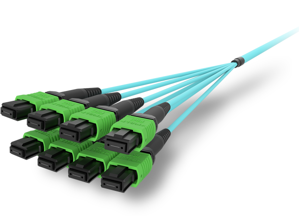
- 📡 MPO / MTP High-Density Cabling — 12 / 24 / 32-fiber for high-density data centers
- ⚡ AOC & DAC Cables — short-reach GPU interconnects, OEM compatible
- 🧩 SFP / SFP+ / SFP28 / QSFP28 Modules — 1G to 100G optical transceivers
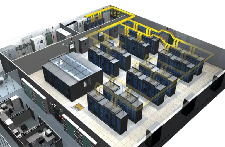
- 📋 Data Center Cabling Solutions — end-to-end design guide
- ❓ Read our FAQ — compatibility, polarity, lead time, MOQ
💬 Get a quote in 12 hours: Contact Candy · WhatsApp +86 188 1445 5697 · candy@abptel.com