Sourcing high-speed optical modules is a pivotal decision for data centers, AI infrastructure, and telecom networks. Misalignments in standards, protocol configurations, or supply chain integrity can derail projects, causing unplanned downtime and escalating costs. To ensure compatibility and operational stability across 100G, 200G, 400G, and 800G ecosystems, we must examine key areas such as standards alignment, host and FEC configuration, meticulous fiber plant design, vendor governance, and rigorous testing. This article provides a structured roadmap to navigate these challenges. From understanding Ethernet standards and FEC modes to managing vendor lock-ins and lifecycle operations, each chapter offers actionable insights tailored to the needs of network engineers, procurement managers, and IT planners. By following this framework, you’ll not only reduce compatibility risks but also optimize cost, reliability, and scalability in your high-speed network infrastructure.
Reducing Compatibility Risk by Aligning Standards, Lanes, and Form Factors Before You Buy
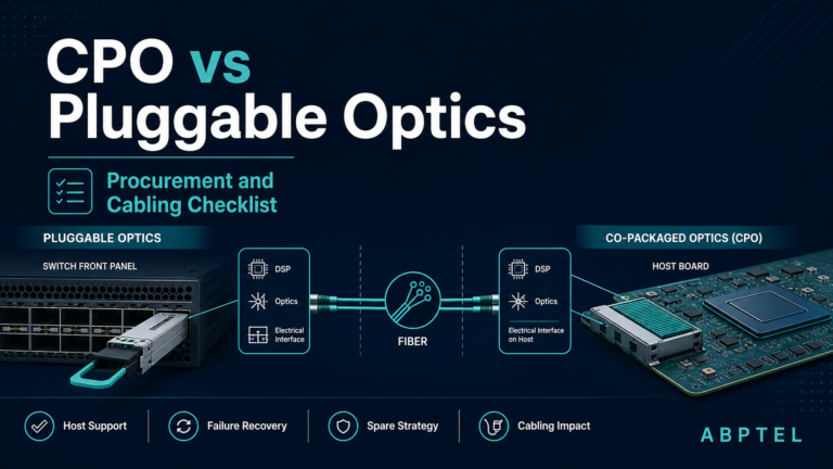
The fastest way to create compatibility problems is to treat a high-speed optical module as a simple speed match. A 400G label alone says very little about whether a module will work in a specific switch, router, or fabric design. Risk drops sharply when sourcing starts with exact standards alignment: the Ethernet PMD, lane architecture, modulation type, connector style, and host form factor must all point to the same design intent.
At the standards level, the safest choice is a module with explicit alignment to the target IEEE or interoperable implementation agreement, not vague claims of equivalence. A 400GBASE-DR4 module, for example, is fundamentally different from 400GBASE-FR4 even though both operate at 400G. DR4 uses parallel single-mode optics over MPO connectivity and is typically specified for 500 m reaches. FR4 uses four wavelengths over duplex LC and is typically specified for 2 km. Those are not interchangeable media options. They drive different cabling, different breakout expectations, and different operational margins. The same logic applies across 100G, 200G, 400G, and 800G generations, where NRZ-based designs give way to PAM4 and lane counts shift from 4x25G to 4x50G, 4x100G, or 8x100G.
That lane architecture matters more than many procurement teams expect. A module may match the port speed but still fail the intended deployment if the electrical and optical lane maps do not line up with the host and fiber plant. A duplex LC 400G optic may fit the business requirement for distance, yet be the wrong choice if the network plan depends on four-way 100G breakout. Parallel-fiber designs often support cleaner migration paths in those cases. This is one reason many teams compare media options early using references such as this guide to 400G DR4, FR4, and LR4 transceivers.
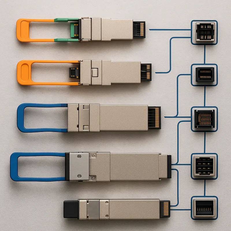
Form factor selection adds another layer of compatibility screening. QSFP28, QSFP56, QSFP-DD, and OSFP are not just physical shells. They define electrical lane counts, management behavior, insertion mechanics, and realistic power envelopes. A module can be standards-compliant and still fail in practice if the host cage does not support its power class, heat load, or mechanical tolerances. Higher-speed and coherent optics make this especially important because thermal headroom becomes part of interoperability, not just reliability.
The sourcing discipline, then, is simple but strict: first lock the required PMD and reach, then confirm modulation and lane architecture, then verify that the chosen form factor fits the host’s electrical and mechanical design. Only after those pieces align does it make sense to evaluate host-side signal processing, FEC behavior, and management interfaces.
Reducing Optical Module Compatibility Risk Through Host ASIC, FEC, and CMIS Alignment
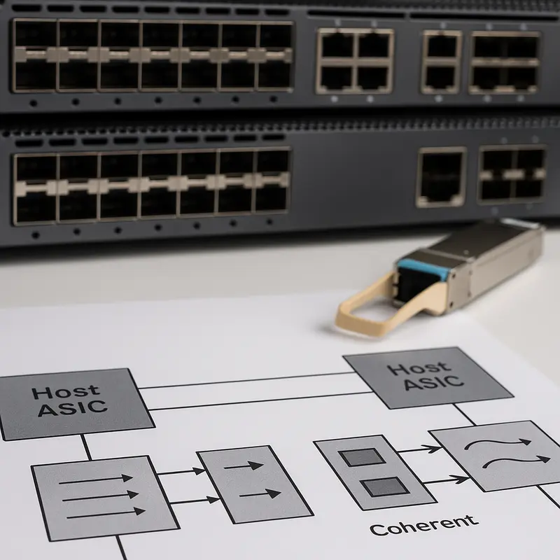
After form factor and PMD selection, the biggest compatibility failures usually happen at the host boundary. A module may be standards-compliant on paper, yet still fail in production because the switch ASIC, port firmware, and network OS expect different electrical behavior, FEC settings, or management responses. That is why sourcing high-speed optical modules must include a host-side validation strategy, not just an optical specification review.
The first checkpoint is the relationship between the host ASIC and the module’s lane architecture. At 100G, many platforms still operate with 25G NRZ electrical lanes. At 200G, 400G, and 800G, PAM4 and 50G or 100G electrical lanes become common, and tolerance for mismatch drops sharply. A host that supports the right speed but not the right electrical mapping, equalization profile, or retimer expectations can produce unstable links, CRC bursts, or ports that never leave training. This is especially important during migration programs, where old and new generations often coexist. Teams planning those transitions should treat host validation as seriously as optics selection, much like the discipline outlined in this guide to migrating 100G to 400G.
FEC and PCS alignment is even less forgiving. With NRZ links, RS-FEC is common, but some hosts still allow legacy no-FEC modes. With PAM4 optics, that flexibility mostly disappears. Many 400G and 800G Ethernet implementations depend on KP4 FEC, and the link budget effectively assumes it. If the host disables FEC, applies the wrong profile, or uses a PCS setting that does not match the selected PMD, pre-FEC BER can rise beyond recoverable limits. The result is often misleading: the port may come up, but packet loss, correctable error spikes, and intermittent flaps appear under load. For sourcing, the practical rule is simple: require evidence that the module was tested on the target ASIC family, NOS release, and exact FEC mode you will deploy.
Management compatibility is the third gate. Older modules rely on simpler memory maps, while newer high-speed pluggables use CMIS with richer state control, diagnostics, and power negotiation. Problems here are often mistaken for hardware defects. In reality, the host may reject the module because it reads an unsupported CMIS revision, mishandles low-power startup, misinterprets compliance codes, or cannot process vendor-specific pages. Before approving any supplier, verify EEPROM fields, power class behavior, DOM readability, alarm thresholds, and state transitions under real host software. This prevents avoidable failures before attention shifts to the fiber plant, connectors, and link budget.
Reducing Compatibility Risk Through Fiber Plant Planning, Connector Discipline, and Real Link Budget Control
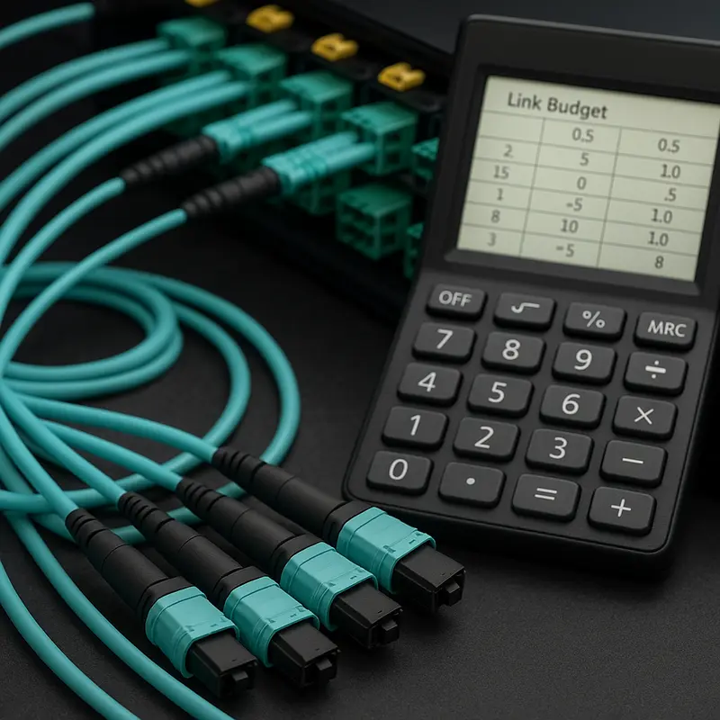
Once the host, FEC, and management layer are aligned, compatibility risk often shifts to the physical path. High-speed optical modules fail in production less from headline speed mismatches than from small fiber-plant mistakes that erode margin. A 400G DR4 link cannot tolerate the same casual patching habits that once passed at lower rates. The media type, connector style, polarity plan, and total insertion loss must match the optical PMD exactly.
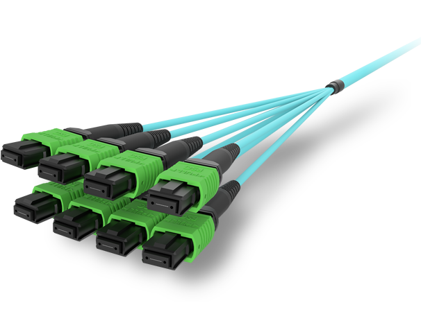
The first rule is simple: buy optics only after confirming the plant they will traverse. Parallel-fiber modules such as DR4 depend on MPO infrastructure and are not interchangeable with duplex LC links. FR4, by contrast, is designed for duplex single-mode fiber and is usually the cleaner choice for structured inter-row runs. Mixing these assumptions creates procurement errors that no software setting can fix. The same applies to multimode versus single-mode decisions. OM3, OM4, OM5, and OS2 are not close substitutes once reach, wavelength, and lane architecture are defined. Teams planning 400G and 800G migrations should also validate polarity and loss budgets early, especially for MPO-based designs, as outlined in this 400G/800G MPO/MTP loss budget and polarity guide.
Connector discipline matters just as much. MPO trunk polarity, key orientation, and pinning errors can swap lanes or kill breakout designs. LC interfaces bring a different risk: mixing UPC and APC creates severe reflection and loss. That kind of mistake can look like a bad module, even when the optic is healthy. Endface contamination is even more common. At PAM4 speeds, a dirty connector can consume enough margin to push a link from stable to intermittent. Inspection and cleaning should therefore be part of receiving, turn-up, and every reconnection event.
Link budget engineering turns these physical choices into a pass or fail decision. Short-reach PAM4 optics often operate with only a few dB of total margin. Every patch panel, cassette, mated pair, and splice counts. Field connector loss of 0.2 to 0.35 dB per pair adds up quickly, and reflection penalties do not always appear in a basic loss reading. For 400G DR4, keeping the total path comfortably within a roughly 3 dB class budget is often the difference between a robust link and one that survives only in the lab. FR4 links allow more room, but patch count and return loss still matter.
The safest sourcing process treats the fiber plant as part of the module specification. Procurement should require a documented path type, connector map, polarity method, expected insertion loss, and cleaning standard before purchase approval. That discipline prevents false RMAs, failed migrations, and costly compatibility surprises later.
Reducing Optical Module Compatibility Risk Through Vendor Coding, Firmware Trust, and Supply Chain Control

As optical compatibility moves beyond fiber reach and connector fit, procurement risk often shifts into less visible layers: EEPROM coding, management behavior, firmware integrity, and supplier governance. A module can match the right PMD, lane count, and power envelope, yet still fail because the host rejects its identity fields or mishandles its management pages. That is why sourcing teams must treat vendor coding as a controlled interoperability parameter, not a purchasing afterthought.
Many platforms inspect module EEPROM contents before enabling the port. They may validate vendor identifiers, compliance codes, connector type, power class, or memory map behavior. If those fields are missing, inconsistent, or loosely programmed, the link may stay down, flap, or enter a degraded state. The risk grows with 400G and 800G optics, where CMIS support, lane telemetry, and power negotiation are more complex than earlier SFF-8636 implementations. Buyers should require a coding policy that matches each target platform exactly, document approved EEPROM profiles by chassis and software release, and reject “universal” coding that masks the real optical interface. This matters especially when comparing DR4, FR4, and coherent variants with very different host expectations. Teams planning larger speed transitions can align this work with a broader 400G transceiver procurement guide.
Security introduces a second compatibility layer. High-speed pluggables now contain controllers, DSPs, and updateable firmware. If firmware provenance is unclear, a module may become both an operational and compliance risk. Signed firmware, secure boot, controlled update workflows, and auditable version tracking should be minimum sourcing requirements. So should software bills of materials and a documented vulnerability response process. In secure environments, I2C write access should be restricted, golden firmware hashes should be retained, and field upgrades should follow formal change control. These measures reduce the chance that a seemingly compatible optic behaves unpredictably after a firmware revision.
Supply chain governance completes the picture. A low unit price means little if parts arrive with inconsistent coding, undocumented component substitutions, or uncertain country-of-origin exposure. A qualified parts list should therefore be maintained by PMD, host platform, and software version, with at least two validated sources where possible. Procurement terms should require lot traceability, anti-counterfeit controls, reliability qualification data, and defined RMA timelines. Regulatory screening also belongs here, including trade restrictions, environmental compliance records, and customer-specific eligibility rules. When these controls are missing, compatibility failures tend to surface late, during deployment or after a network software upgrade. When they are formalized, the next phase of testing and lifecycle validation becomes faster, cleaner, and far more predictable.
Proving Compatibility Before Production: A Testing, Validation, and Lifecycle Operations Framework for High-Speed Optical Modules

A sourcing decision is only as strong as the validation process behind it. After coding, security, and supply-chain controls are set, the next step is proving that a module will behave correctly in the actual host, cabling plant, and operating environment. That means acceptance testing cannot stop at a successful link-up event. A port can come up and still carry hidden risk through marginal pre-FEC performance, unstable thermal behavior, or management interface inconsistencies that appear only under sustained traffic.
A practical framework starts before optics are inserted. Host ports should be staged with the correct PCS and FEC profile for the target PMD, especially for PAM4 links that depend on KP4 to turn acceptable pre-FEC BER into clean post-FEC operation. Breakout ports also need their logical partitions defined in advance. Once the module is installed, validation should combine management checks with traffic and signal-quality checks. Read the module identity, compliance codes, power class, temperature, and lane telemetry. Confirm that the host recognizes the optics without fallback behavior, low-power lock, or unexpected alarms. Then move to error-performance testing with PRBS31 for NRZ or PRBS31Q for PAM4, and watch pre-FEC counters over time rather than taking a single snapshot.
Physical-layer verification matters just as much. Every acceptance flow should include endface inspection and cleaning, insertion-loss measurement, and OTDR analysis when the budget is tight. Many compatibility incidents are blamed on modules when the actual cause is polarity error, contaminated connectors, or patching that consumes too much margin. For teams planning parallel-fiber links and breakouts, a detailed review of 400G/800G MPO/MTP loss budget and polarity pitfalls helps expose those hidden failure points early. On short-reach PAM4 links, even modest excess loss or reflection can erase the limited optical budget and push the link toward intermittent correction storms.
Lifecycle operations should extend the same discipline beyond turn-up. Define pass criteria in measurable terms: stable link at target speed, pre-FEC BER within threshold, zero post-FEC errors across a fixed test window, readable telemetry, and no thermal throttling at ambient extremes. Store baseline DOM snapshots and fiber-loss records at deployment. Trend temperature, receive power, and transmit bias current over time to catch drift before service impact appears. Pair that with controlled firmware changes, regression testing after NOS upgrades, clear RMA targets, and a spare strategy sized to criticality. Compatibility risk drops sharply when validation becomes a repeatable operational system rather than a one-time lab exercise.
Final thoughts
Reducing compatibility risks when sourcing high-speed optical modules requires a multi-disciplinary approach. By aligning standards, ensuring host compatibility, optimizing fiber plant design, and enforcing vendor security and testing regimes, your organization can meet operational goals with confidence. Planning for scalability and contingencies not only minimizes risk but also supports long-term infrastructure success. Leveraging the framework detailed in this guide will give your team a proven recipe for seamless interoperability and uptime in increasingly complex 100G–800G ecosystems.
Talk to ABPTEL about high-speed optics, MTP/MPO cabling, and data center interconnect solutions to strengthen your infrastructure.
Learn more: https://abptel.com/contact/
About us
ABPTEL provides high-speed optical transceivers, MTP/MPO cabling systems, DAC and AOC cables, PoE switches, FTTA solutions, and fiber tools for data center, AI, telecom, and network infrastructure projects.
Talk to ABPTEL
Looking for the right optical hardware for your AI data center, GPU cluster, or FTTA project? ABPTEL ships from Shenzhen with OEM/ODM support, fast lead times, and engineering-level pre-sales advice.
- 🔥 400G & 800G OSFP / QSFP-DD Transceivers — for AI training fabrics and hyperscale spine-leaf
- 📡 MPO / MTP High-Density Cabling — 12 / 24 / 32-fiber for high-density data centers
- ⚡ AOC & DAC Cables — short-reach GPU interconnects, OEM compatible
- 🧩 SFP / SFP+ / SFP28 / QSFP28 Modules — 1G to 100G optical transceivers
- 📋 Data Center Cabling Solutions — end-to-end design guide
- ❓ Read our FAQ — compatibility, polarity, lead time, MOQ
💬 Get a quote in 12 hours: Contact Candy · WhatsApp +86 188 1445 5697 · candy@abptel.com