The transition to 800G Ethernet represents a quantum leap for high-density data centers, driven by the need to scale networks for AI, machine learning, and hyperscale applications. Success depends not only on adopting cutting-edge switch silicon and optics but also on meticulous planning across cabling, thermal management, power, and operations. Engineers, planners, and managers must navigate challenges in signal integrity, network architecture, and sustainability to achieve optimal scalability and efficiency. This article addresses these complexities in five interconnected pillars: optical standards and module choices, structured cabling, thermal and power engineering, fabric architecture, and a forward-looking economic and supply chain strategy. Read on for actionable insights on how to future-proof your data center for seamless 800G deployment while staying aligned with operational excellence and long-term sustainability.
Choosing 800G Optics and Electrical Interfaces for High-Density Data Center Readiness

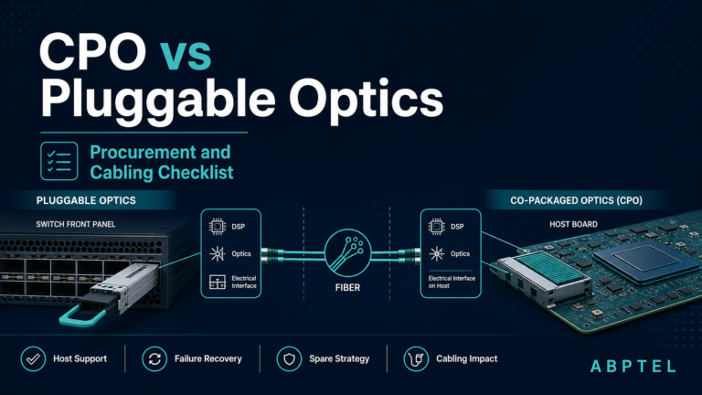
Preparing for 800G starts with a simple truth: port speed alone does not determine deployment success. The real constraint is how well your optical modules, host electrical lanes, and management standards fit the physical and thermal realities of a dense data center. Most current 800G designs are built on 8 x 100G electrical lanes using 112G PAM4 signaling, defined by IEEE 802.3ck and aligned with OIF CEI-112G expectations. That matters because the host-to-module channel must be clean enough for PAM4 to operate with acceptable pre-FEC error rates before forward error correction restores the link to production quality.
This is why module choice cannot be separated from board design or switch selection. Retimed optics offer better tolerance to channel loss, crosstalk, and host variation, but they consume more power and add some latency. Linear-drive optics lower module power and can improve energy per bit, yet they demand very short, very clean electrical paths and disciplined interoperability testing. In high-density rows, those trade-offs affect more than link budgets. They shape airflow, faceplate density, and even whether a platform can sustain full population under warm inlet conditions.
Form factor is equally strategic. OSFP generally provides more thermal headroom, which is often decisive for higher-power 800G modules. QSFP-DD800 preserves a more compact footprint and can simplify migration in environments already standardized on that style. The right answer depends on whether your design priority is maximum thermal margin or tighter front-panel density. Teams comparing these paths often begin with a broader review of 400G vs 800G transceiver choices, then narrow decisions by reach, power class, and breakout needs.
Within the data center, the most common optical options map cleanly to distinct deployment envelopes. 800G-SR8 fits short multimode runs where cost per port matters and structured parallel optics are already in place. 800G-DR8 is the workhorse for single-mode links up to 500 meters and offers flexible 8 x 100G breakout options. 800G-2xFR4 reduces fiber count and supports 2 x 400G migration paths over duplex single-mode infrastructure. These are not interchangeable defaults. They reflect different assumptions about connector strategy, future breakout plans, and operational tolerance for loss and reflection.
The standards layer also extends into operations. CMIS support is essential for power-class awareness, lane diagnostics, alarms, PRBS controls, and firmware handling. Without consistent module telemetry and management behavior, mixed-vendor 800G environments become harder to validate and much harder to automate. That is why early qualification should focus not only on optical reach and BER, but also on host compatibility, thermal behavior at full density, and firmware governance. Once those decisions are set, the next challenge becomes the cable plant that must carry them reliably at scale.
Designing an 800G-Ready Cabling Plant: Connectors, Loss Budgets, and Breakout Paths That Scale

The jump to 800G is not only a transceiver decision. It is a cabling plant decision that will either preserve flexibility or lock the data center into expensive rework. In high-density environments, the physical layer must support current link classes, predictable operations, and a clean migration path from 400G and 100G endpoints.
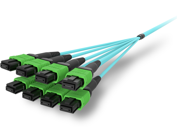
For parallel optics, MPO-16 has become the practical baseline because it aligns with 8-lane 800G designs without wasting fibers. That matters for both 800G-SR8 over multimode and 800G-DR8 over single-mode. Using older MPO-24 infrastructure can still work, but it often leaves dark fibers and adds complexity in cassettes and polarity management. For WDM links such as 800G-2xFR4, LC duplex remains the more efficient choice, especially when fiber count matters more than breakout flexibility. The planning question is simple: do you want the plant optimized for lane-parallel fanout, or for lower fiber counts and cleaner duplex patching?
That choice drives connector policy, polarity rules, and insertion-loss discipline. SR8 channels have tight multimode budgets, so every extra mating pair consumes valuable margin. DR8 is more forgiving on reach, but less forgiving on reflections and connector quality. In practice, that means low-loss components, fewer patch points, and APC-based single-mode MPO where return loss matters. Teams that treat patch fields as unlimited convenience often discover that 800G exposes every sloppy decision made at 100G and 400G. A structured approach to loss budgeting and polarity control is essential, especially when planning trunks, cassettes, and parallel breakouts at scale. For a deeper look at these migration pitfalls, see this guide to 400G and 800G MPO/MTP loss budget and polarity.
Breakout architecture is where good cabling design creates real business value. 800G to 2x400G supports gradual server and leaf upgrades without forcing full fabric replacement. 800G to 8x100G remains useful for storage, legacy leaf fanout, and staged migrations. DR8 is especially attractive here because the same single-mode plant can serve immediate 100G breakout needs and later be repurposed for native 800G links. SR8 can offer lower cost over short reaches, but multimode plants become harder to scale cleanly in very dense halls.
The physical layout also matters. Dense cable bundles can block airflow and complicate maintenance, so routing, bend radius, and labeling should be treated as design inputs, not installation afterthoughts. A well-prepared 800G cabling plant reduces re-cabling events, shortens turn-up time, and gives the thermal and power teams a cleaner platform to support the next stage of density.
Engineering the Rack for 800G: Thermal, Power, and Mechanical Readiness in High-Density Data Centers
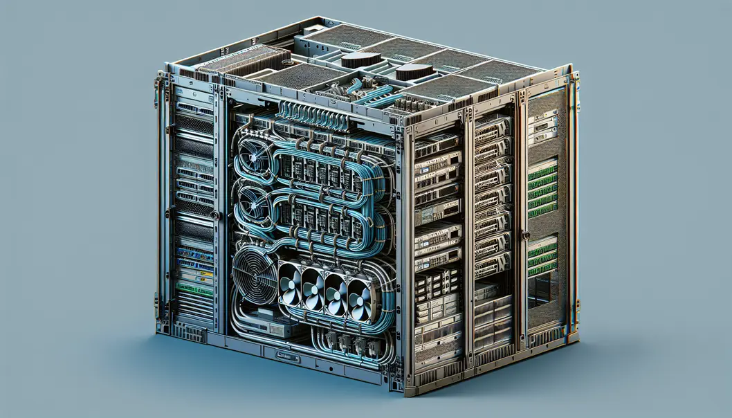
Moving from cable design to live 800G deployment, the next constraint is no longer only optical reach. It is whether the rack, chassis, and row can safely absorb the heat and power density that 800G creates. In practice, 800G readiness often fails at the mechanical layer first. A switch may support the port count on paper, yet struggle once every slot is populated with high-power optics, dense front-panel cabling, and sustained east-west traffic.
A fully loaded high-density switch can draw well above 2 kW at the chassis level. Optics account for a large share of that budget. In 51.2T platforms, dozens of 800G modules can consume more than 1 kW before the switch ASIC, memory, fans, and power conversion losses are included. That changes rack planning immediately. Branch circuits, PDUs, and PSU redundancy must be sized for worst-case draw, not average lab conditions. A practical design target includes at least 20 percent margin for hot-plug events, fan ramping, and workload spikes.
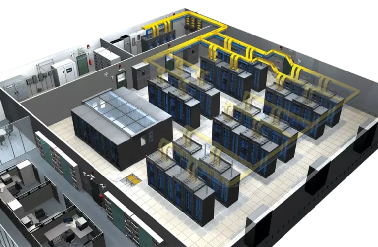
Thermal design is just as unforgiving. High-density 800G faceplates concentrate heat at the front of the chassis, exactly where cable bundles can choke airflow. Module case temperature, inlet temperature, and fan duty cycle become operational variables, not passive environmental details. Many 800G modules can tolerate high case temperatures, but that does not mean they should run near the limit. Lower inlet temperatures preserve optical margin, reduce fan noise, and improve long-term reliability. In warm aisles, that often pushes teams toward stronger containment, rear-door heat exchangers, or selective liquid assistance for the row.
Form factor choice also becomes an engineering decision, not a purchasing preference. Larger module formats usually provide more thermal headroom and stronger heatsinking. Smaller formats improve faceplate density but can tighten the cooling envelope. The right answer depends on optic power class, airflow direction, and how much cable congestion the front panel will see during steady-state operations. This is one reason many teams compare density and heat together when reviewing 400G vs 800G transceivers, rather than treating speed alone as the upgrade driver.
Mechanical details matter more than they seem. Latch pressure, heatsink contact, bend-radius clearance, and cable-manager placement can all affect thermal stability. Computational airflow modeling is worth the effort for dense 1RU and 2RU designs, especially where every blocked intake path raises module temperature. Align chassis airflow with row containment, leave service loops that do not blanket vents, and validate that populated racks remain maintainable. Those steps create the stable hardware envelope needed for the next stage: architecture choices, migration patterns, and operational validation under real traffic.
Designing the 800G Migration Path: Fabric Architecture, Breakouts, and Proof Before Production

As 800G moves into high-density data centers, architecture decisions must balance immediate scale with a clean migration path from 100G, 200G, and 400G estates. In most modern leaf-spine designs, 800G is not introduced as an isolated speed upgrade. It becomes the new lane aggregation layer for east-west traffic, especially where AI training, NVMe-oF, and dense microservices produce persistent incast and all-reduce pressure. A 51.2T spine with 64×800G ports can collapse fabric tiers, increase radix, and preserve non-blocking behavior without multiplying switch count. That matters because fewer stages mean fewer optics, fewer failure points, and simpler traffic engineering.
The practical migration pattern is usually hybrid, not wholesale. Many operators begin by using 800G ports as 2×400G links toward existing leaves or accelerator hosts, then shift those same ports to native 800G as server and switch generations catch up. Parallel optics also make 8×100G fanout viable where legacy endpoints remain in service. This is why media choice must align with the future state, not just the first deployment wave. DR8 often fits staged migrations because the same single-mode plant can support breakout today and point-to-point 800G later. By contrast, 2xFR4 reduces fiber count and suits structured duplex cabling, making it attractive where 400G dual-port transitions dominate. Teams weighing these options can compare port roles, reach, and density tradeoffs in this overview of 400G vs 800G transceivers.
Architecture also has to account for workload behavior, not just link math. AI clusters often demand high-radix Clos fabrics, shallow buffers, and carefully tuned congestion controls. If the environment uses RoCEv2, small mistakes in PFC, ECN, or buffer policy can erase the benefit of faster optics. For general cloud fabrics, VXLAN and EVPN remain common, but 800G raises the cost of hidden oversubscription and poor lane mapping. Breakout conventions, logical port splits, and lane ordering should therefore be validated early across host platforms, network operating systems, and module suppliers.
Operational validation is what turns a design into a deployable standard. Before production traffic, run line-rate PRBS on each lane, verify pre-FEC margins, and watch corrected codeword trends rather than waiting for hard failures. Optical power, bias current, and case temperature should be streamed through CMIS telemetry into the same observability stack used for switch health. Traffic testing should include mixed packet sizes, bursty incast, and failure scenarios that reflect real cluster behavior. In dense 800G fabrics, success depends less on whether links come up and more on whether they stay stable under pressure, drift, and change.
Preparing 800G Data Centers for Real-World Scale: Cost, Supply Resilience, and Sustainable Growth

As 800G moves from pilot fabrics into mainstream deployment, planning cannot stop at port speed, optics reach, or switch density. High-density data centers succeed or fail on whether the business model, procurement strategy, and sustainability profile can support that technical leap. The raw performance case is compelling: 800G can reduce switch count, shrink fabric layers, and improve bandwidth per rack unit. Yet those gains only materialize when teams model cost per delivered bit, not just transceiver price or chassis list cost.
In practice, the strongest economic case for 800G often comes from consolidation. Fewer devices can mean fewer uplinks, fewer patching events, lower management overhead, and reduced space pressure in dense rows. Power still dominates operational expense. A chassis drawing around 2 kW can cost thousands per year to run before cooling overhead is added. Because optics often account for a large share of platform power, module choice has a direct effect on long-term operating cost. That is why decisions around retimed optics, lower-power alternatives, and breakout strategies should be tied to a full fabric TCO model. For teams comparing upgrade paths, this context aligns well with broader guidance on 400G vs 800G transceivers.
Supply chain planning is equally strategic. 800G optics depend on advanced packaging, DSPs, lasers, and high-speed electrical components that can face uneven lead times. A deployment plan that assumes continuous availability is fragile by default. Dual-sourcing each major optic class, qualifying more than one form factor where practical, and holding buffer stock for failure-prone or long-lead items can prevent rollout delays from turning into capacity shortages. The same logic applies to structured cabling parts, MPO components, and high-density cooling accessories. Standardization lowers operational complexity, but over-concentration raises sourcing risk.
Geopolitics adds another layer. Trade restrictions, export controls, regional manufacturing concentration, and logistics disruptions can all reshape pricing and delivery windows with little warning. For 800G programs, this means procurement should not be treated as a late-stage purchasing task. It belongs in the architecture phase, alongside interoperability and thermal validation. Vendor qualification, firmware trust, and supply continuity should be reviewed together.
Sustainability goals also become more concrete at 800G densities. Higher bandwidth can improve energy per bit, but it also concentrates thermal load into fewer racks and faceplates. That makes cooling design, airflow discipline, and optics power efficiency part of the environmental equation. Teams that track PUE, reuse displaced 400G assets, reduce installation waste through pre-terminated cabling, and train staff to avoid connector damage can improve both carbon outcomes and operating efficiency. In other words, preparing for 800G is not only about scaling bandwidth. It is about building a deployment model that remains affordable, obtainable, and responsible as density rises.
Final thoughts
Preparing for 800G deployments demands a multidisciplinary approach. From optics and cabling to thermal and operational readiness, the move to 800G scales performance while introducing unique challenges. By aligning your design with the latest standards and investing in scalable, sustainable architectures, you can future-proof your data centers for AI workloads, high-performance fabrics, and rising network demands. Pay attention to thermal optimization, structured cabling, effective cost modeling, and secure supply chains to ensure your deployment is both reliable and forward-compatible.
Talk to ABPTEL about high-speed optics, MTP/MPO cabling, and data center interconnect solutions today.
Learn more: https://abptel.com/contact/
About us
ABPTEL provides high-speed optical transceivers, MTP/MPO cabling systems, DAC and AOC cables, PoE switches, FTTA solutions, and fiber tools for data center, AI, telecom, and network infrastructure projects.
Talk to ABPTEL
Looking for the right optical hardware for your AI data center, GPU cluster, or FTTA project? ABPTEL ships from Shenzhen with OEM/ODM support, fast lead times, and engineering-level pre-sales advice.
- 🔥 400G & 800G OSFP / QSFP-DD Transceivers — for AI training fabrics and hyperscale spine-leaf
- 📡 MPO / MTP High-Density Cabling — 12 / 24 / 32-fiber for high-density data centers
- ⚡ AOC & DAC Cables — short-reach GPU interconnects, OEM compatible
- 🧩 SFP / SFP+ / SFP28 / QSFP28 Modules — 1G to 100G optical transceivers
- 📋 Data Center Cabling Solutions — end-to-end design guide
- ❓ Read our FAQ — compatibility, polarity, lead time, MOQ
💬 Get a quote in 12 hours: Contact Candy · WhatsApp +86 188 1445 5697 · candy@abptel.com