How Do SFP Optical Transceivers Fit Into Modern Fiber Networks?
Networks grow faster every quarter. Buyers must pick the right SFP, yet spec sheets feel cryptic. I once mixed a BiDi with duplex patch cords. The link died and clients yelled. After a 3 a.m. re-patch I wrote this checklist so no one repeats my night-shift lesson.
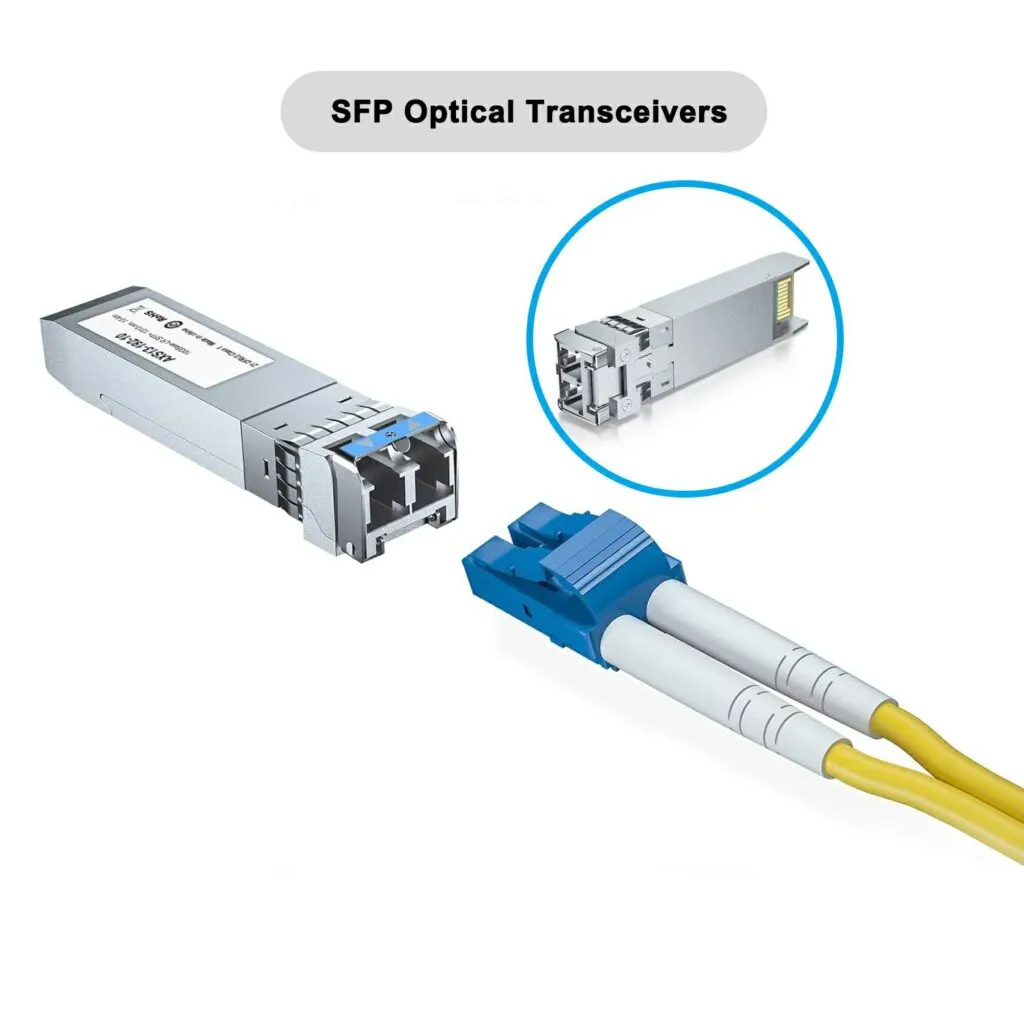
An SFP turns electrical bits into light. Each flavor—duplex, BiDi, CWDM—targets a clear job. When the module, fiber, and budget line up, the link works the first time and never shows a “flap” in syslog.
Over a decade I have installed 1 000-plus optics across data rooms, telco huts, and street cabinets. The same four questions decide every purchase:
- How will the SFP mate with the MPO trunk behind it?
- Which duplex/BiDi/CWDM mode saves the most fiber?
- Does the reach spec survive real loss, dust, and bends?
- What is the true cost per port when power and trenching join the bill?
The sections below break each question into tables you can drop into any RFQ.
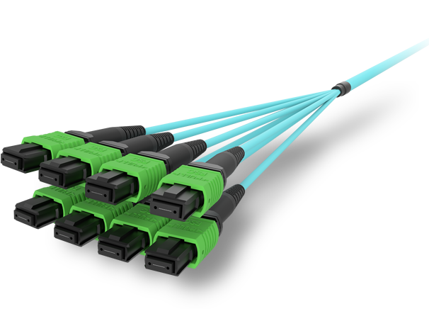
Integrating SFPs With MPO/MTP Backbone Cabling?
Edge switches present LC ports, while structured cabling now ships as high-density MPO trunks. The mismatch looks scary until you see the building blocks.
Answer: deploy a Base-8 cassette1 or fan-out harness that converts one MPO-8 to four LC duplex legs, then keep polarity Method B2 so no fibers strand and no Tx/Rx swap.
Dive Deeper
Fan-Out Hardware at a Glance
| Device | MPO Ports | LC Ports | Fiber Grade | Primary Use |
|---|---|---|---|---|
| Base-8 cassette1 | 1 × MPO-8 | 4 × LC duplex | OM4 / OS2 | 40 G → 4 × 10 G |
| Harness (0.5 m) | 1 × MPO-8 | 4 × LC duplex | OM4 patch | Leaf-TOR fan-out |
| Harness (5 m) | 1 × MPO-8 | 8 × LC simplex | OS2 | BiDi pairs in ODF |
| Panel w/ Shutter | 4 × MPO-8 | 16 × LC duplex | Mixed | Multi-tenant MMR |
Cleaning & Test Routine
- Push an MPO-specific lint-free swab, rotate twice.
- Inspect under 400× scope; end-face debris ≤ 5 µm.
- Run Tier-1 test: IL < 1.3 dB, RL > –25 dB.
- Label each LC tail “Rack X / Port Y” before lift.
Bend-Radius Watch
- MPO trunk: ≥ 7.5 × OD (≈ 60 mm on 8 mm jacket).
- LC harness leg: ≥ 5 × OD (≈ 10 mm on 2 mm patch).
Drop below these and micro-bends add stealth loss that DOM alarms cannot see.
Duplex, BiDi and CWDM SFPs—When to Use Each?
Three optics solve three boundaries: direction, fiber scarcity, and channel scale.
- Duplex SR/LR use two cores—simple, cheap, everywhere.
- BiDi uses one core with 1310 ↔ 14903 WDM to halve fiber.
- CWDM packs 18 channels across 1270–16104 on one pair to dodge trench work.
Dive Deeper
How to Pick Fast
| If… | Then choose | Because |
|---|---|---|
| Fiber is plentiful and distance ≤ 10 km | Duplex SR/LR | Lowest $/port |
| Only one spare core exists | BiDi | Halves fiber count |
| Many 10 G links ride a metro ring | CWDM | Adds channels without new duct |
Hidden Pitfalls
- BiDi mix-up: Plug an “A-side” into a “B-side” port and the link never comes up. Label BOTH ends.
- CWDM loss budget: The mux/demux adds 1.2 dB; ER optics rated 14 dB now have 12.8 dB left. Cleanliness becomes critical.
- Reflections: BiDi and CWDM both hate reflectance > –27 dB. Use APC connectors on long single-mode runs.
Single-Mode vs Multi-Mode Reach Tables up to 40 km?
Spec sheets claim “300 m SR” or “10 km LR,” yet ignore real-world splice trays, dirty adapters, and aging.
| Optic | Fiber | Reach | Link Loss Budget |
|---|---|---|---|
| 1 G SX | OM2 | 260 m | 4.0 dB |
| 10 G SR | OM4 | 400 m5 | 2.6 dB |
| 10 G LR | OS2 | 10 km6 | 6.3 dB |
| 10 G ER | OS2 | 40 km | 14 dB |
| 25 G LR | OS2 | 10 km | 5 dB |
| BiDi 10 G | OS2 | 40 km | 14 dB |
| CWDM 10 G | OS2 | 80 km w/ amp | 24 dB |
SR/VR optics on multi-mode run out of steam when bandwidth × distance > “EMB spec”. OM4’s 4 700 MHz·km EMB7 gives headroom for 100 m 25 G SR too.
Safety Margin Rule
Take vendor budget – (aging + dust + modal penalty).
- 3 dB for dust and bends.
- 0.3 dB splice each.
If result < 0 dB, pick a higher-budget optic.
Cost-per-Port Analysis for Edge, Access & Core Layer
Price per port drops every year, yet trenching and power stay steady. Look at total.
CapEx vs OpEx Blend
| Layer | Speed | Optic | Module ($) | Switch Port ($) | 5-yr Power ($) | 5-yr Port Total |
|---|---|---|---|---|---|---|
| Edge | 1 G | SX duplex | 18 | 45 | 4 | 67 |
| Access | 10 G | LR duplex | 62 | 120 | 12 | 194 |
| Access | 10 G | BiDi 10 km | 89 | 120 | 12 | 221 |
| Core | 25 G | LR | 140 | 220 | 18 | 378 |
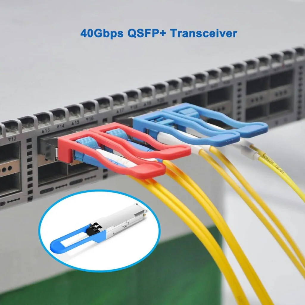
| Core | 40 G | QSFP+ SR4 | 160 | 400 | 24 | 584 |
| Metro | 10 G | CWDM 40 km | 280 | 180 | 14 | 474 |
Power & Cooling Notes
- 1 W at 0.10 $/kWh over five years ≈ 4 $.
- LR draws 1.5 W, BiDi 1.8 W, CWDM 2.8 W.
- High-density TOR switch fans add 0.6 W per optic to cooling.
Fiber Avoidance Math
BiDi premium (89 $ – 62 $) = 27 $.
Trench bypass > 27 $ / m? Break-even at 4 m of avoided duct when cost hits 6.80 $ / m.
Conclusion
Tie SFPs to MPO trunks with clean fan-outs, pick duplex/BiDi/CWDM based on fiber scarcity, sanity-check every reach claim against real loss, then run full port economics. When these four boxes turn green, links light the first time, budgets stay on track, and no one calls you at 3 a.m.
Detailed port map and wiring spec for Base-8 MPO cassettes. ↩ ↩
TIA-568 diagram of polarity Method B for straight-through MPO trunks. ↩
Vendor app note explaining BiDi SFP operation at 1310/1490 nm over one core. ↩
ITU-T G.694.2 table defining CWDM channels 1270–1610 nm. ↩
IEEE 802.3 clause giving 10GBASE-SR maximum 400 m reach on OM4. ↩
IEEE 802.3 clause listing 10GBASE-LR reach of 10 km on OS2. ↩
ISO/IEC data sheet listing OM4 EMB of 4 700 MHz·km at 850 nm. ↩
Talk to ABPTEL
Looking for the right optical hardware for your AI data center, GPU cluster, or FTTA project? ABPTEL ships from Shenzhen with OEM/ODM support, fast lead times, and engineering-level pre-sales advice.
- 🔥 400G & 800G OSFP / QSFP-DD Transceivers — for AI training fabrics and hyperscale spine-leaf
- 📡 MPO / MTP High-Density Cabling — 12 / 24 / 32-fiber for high-density data centers
- ⚡ AOC & DAC Cables — short-reach GPU interconnects, OEM compatible
- 🧩 SFP / SFP+ / SFP28 / QSFP28 Modules — 1G to 100G optical transceivers
- 📋 Data Center Cabling Solutions — end-to-end design guide
- ❓ Read our FAQ — compatibility, polarity, lead time, MOQ
💬 Get a quote in 12 hours: Contact Candy · WhatsApp +86 188 1445 5697 · candy@abptel.com