MPO Polarity Type A, B, C: The Complete Guide to Getting It Right Every Time
Polarity is the most common reason a freshly cabled data center link doesn’t work on day one.
The fiber is good. The transceivers are good. The cable insertion loss tests fine. But signal won’t pass — because transmit on one end connects to transmit on the other.
I’ve seen this happen on projects ranging from a 12-port test lab to a 10,000-port hyperscale deployment. Every time, the root cause is the same: MPO polarity wasn’t specified and verified before cables were ordered.
This guide gives you a complete, practical understanding of MPO polarity Types A, B, and C — what they mean, how to choose the right one for your system, and how to avoid the mistakes that waste weeks of troubleshooting time.
—
Table of Contents
1. Why MPO Polarity Matters 2. The Basics: How MPO Fiber Numbering Works 3. Polarity Type A — Straight-Through 4. Polarity Type B — Reversed 5. Polarity Type C — Pair-Flipped 6. Which Polarity Type to Use: Decision Framework 7. Polarity in Cassette-Based Systems 8. The 3 Questions to Confirm Before You Order 9. Troubleshooting: My Link Is Down After Installation 10. FAQs
—
Why MPO Polarity Matters
Every optical link needs transmit (Tx) on one end connected to receive (Rx) on the other. With a simple duplex LC cable, this is trivial — the two fibers cross over at one end.
With MPO connectors carrying 12, 16, or 24 fibers, the fiber-to-fiber mapping becomes critical. An MPO-12 connector has 12 fiber positions (numbered 1–12). If position 1 at end A connects to position 1 at end B, the link is straight-through. If position 1 at end A connects to position 12 at end B, the link is reversed.
Transceivers don’t care which “method” you use — they just need Tx connected to Rx. The polarity method defines how you achieve that mapping across your entire channel, including trunk cables, cassettes, and jumpers.
The critical rule: polarity must be consistent and documented end-to-end. Mixing polarity types in a single channel without compensation is the most common cause of link failure.
—
The Basics: How MPO Fiber Numbering Works
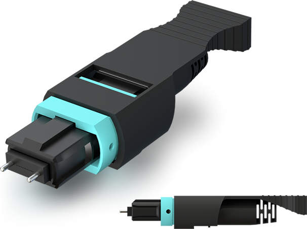
MPO connectors have a key on the connector body. Fiber position numbering is defined relative to the key:
- Key-up orientation: Position 1 is at the left, position 12 (or 16/24) is at the right
- Key-down orientation: Position 1 is at the right, position 12 is at the left
This is not just academic. When you mate two MPO connectors, whether the key is up or down on each side determines whether the fiber mapping is straight or reversed.
Remember this: when two MPO connectors mate face-to-face (as they do in an adapter), position 1 on side A connects to position 1 on side B only if both connectors have the same key orientation. If one is key-up and the other key-down, position 1 connects to position 12.
This is the physical foundation for all three polarity types.
—
Polarity Type A — Straight-Through
How it works: An MPO Type A cable has the key-up on one end (End A) and key-down on the other end (End B). Fiber position 1 at End A connects to position 1 at End B. The fiber mapping is straight-through: 1→1, 2→2, 3→3 … 12→12.
Physical result at the adapter: When End A (key-up) mates with End B (key-down) through an adapter, the positions align correctly because the key-flip compensates for the face-to-face reversal.
What this means for your signal: If your Tx is on position 1 at End A, your signal arrives at position 1 at End B. For the link to work, the device at End B must be listening (Rx) on position 1.
When Type A is used:
- In system designs where the polarity reversal (Tx-to-Rx crossover) is handled by the cassette or patch panel, not the trunk cable
- In QSFP-based 40G and 100G SR4 systems where the transceiver internally handles the Tx/Rx pairing across adjacent fiber pairs
- As the default trunk cable type in most structured cabling designs (the crossover is done at the cassette level)
Identifying a Type A cable: Look at the connector keys. On a straight Type A cable, one end is key-up and the other is key-down. The jacket is often printed with “Type A” or has a yellow dot on the key-up end.
—
Polarity Type B — Reversed
How it works: An MPO Type B cable has key-up on both ends. Because both connectors face each other through an adapter, position 1 at End A connects to position 12 at End B. The mapping is fully reversed: 1→12, 2→11, 3→10 … 12→1.
What this means for your signal: If your Tx is on position 1 at End A, your signal arrives at position 12 at End B. For the link to work, Rx at End B must be on position 12. This reversal is what enables straight-through signal transmission: in most duplex-pair-based transceivers, Tx fibers and Rx fibers are at opposite ends of the connector (positions 1–6 Tx, positions 7–12 Rx), so the full reversal crosses Tx to Rx correctly.
When Type B is used:
- In direct cable connections (trunk-to-trunk) without intermediate cassettes
- In CPRI links, 100G-PSM4, and some 400G-DR4 single-mode applications
- In proprietary vendor systems that specify Type B throughout
Identifying a Type B cable: Both connectors are key-up. The jacket is often printed with “Type B” or has a blue or red dot at both ends.
Critical caution: Type B and Type A cables look almost identical on the shelf. The key orientation difference is subtle and easy to miss under the time pressure of installation. Always mark cables clearly and test before buttoning up.
—
Polarity Type C — Pair-Flipped
How it works: An MPO Type C cable is similar to Type A (key-up on one end, key-down on the other) but with a twist: adjacent fiber pairs are swapped within the cable. Positions 1 and 2 are swapped, positions 3 and 4 are swapped, and so on. The mapping is: 1→2, 2→1, 3→4, 4→3 … 11→12, 12→11.
When Type C is used:
- In duplex-pair-based transceivers where signal flows as Tx/Rx pairs and a pair-level swap (rather than a full reversal) is needed
- In some 40G-SR4 and 100G-SR4 implementations, particularly with older cassette designs
- When your system design specifically calls for pair-flipped polarity to achieve Tx-to-Rx crossover
Why Type C is less common now: Most modern cassette-based systems handle polarity compensation at the cassette, making Type C trunk cables unnecessary. Type A trunks with properly designed cassettes have largely replaced Type C in new deployments. However, if you’re extending or matching an existing installation, you may encounter Type C in the field.
—
Which Polarity Type to Use: Decision Framework
The right choice depends on three factors: (1) whether you’re using cassettes, (2) what transceivers you’re running, and (3) what the switch/router vendor specifies.
Step 1: Are you using a cassette-based breakout?
Yes (cassette between trunk and LC patch leads):
- Use Type A trunk cables + properly designed cassettes
- The cassette handles the Tx/Rx crossover — the trunk is straight-through
- This is the most common and most recommended method for structured cabling
No (direct MPO-to-MPO or MPO to breakout harness):
- For 40G-SR4 / 100G-SR4 QSFP transceivers with internal Tx/Rx pairs: use Type B (full reversal)
- For CPRI / 100G-PSM4 / 400G-DR4 single-mode: verify your transceiver datasheet for Tx/Rx lane assignments, then choose accordingly
Step 2: What do your transceivers specify?
Always check the transceiver datasheet for the fiber lane map. It will show which positions are Tx and which are Rx. Match your polarity method to ensure Tx on the source device connects to Rx on the destination device.
As a general rule for common platforms in 2026:
- Cisco / Arista / Juniper 40G-SR4, 100G-SR4: Type A trunks + Type A cassettes ✓
- Nvidia NVL / A100 / H100 GPU clusters (400G/800G OSFP): Verify with Nvidia cabling guide — most specify Type A trunks with compatible cassettes
- Custom passive breakout harnesses: Type B or Type C depending on harness design
> 💬 Not sure what your transceivers require? Send Candy your transceiver part numbers on WhatsApp and get a polarity recommendation within 24 hours.
—
Polarity in Cassette-Based Systems
Cassettes are modular breakout units that sit in a patch panel. They accept one or two MPO trunk cables on the back and present LC duplex ports on the front. The cassette handles the Tx/Rx crossover internally.
How it works with Type A trunks: 1. Trunk cable runs from Switch A to the distribution frame (Type A, straight-through) 2. At the distribution frame, the trunk plugs into a cassette (back of panel) 3. The cassette internally crosses Tx fibers to Rx positions as it breaks out to LC ports 4. A short LC duplex patch lead connects the cassette LC port to the next device
The cassette is designed so that a Type A trunk end-to-end, with cassettes at both ends, always delivers Tx→Rx crossing at the link level — regardless of which cassette port you plug into.
Key rule: cassettes are not all the same. A cassette designed for Type A trunks is different from one designed for Type B. Using a Type B cassette with a Type A trunk inverts your polarity unexpectedly. Specify trunk type when ordering cassettes, not just fiber type and connector type.
ABPTEL’s MTP/MPO cassettes are available in Type A and Type B configurations. Specify at order time — we can’t tell from a part number change request after the fact.
—
The 3 Questions to Confirm Before You Order
Question 1: Is this a direct-attach or cassette-based system?
Direct-attach (trunk runs directly between switch MPO ports, no cassette): use Type B for most modern transceiver types.
Cassette-based structured cabling (trunk runs to patch panel): use Type A trunks + matched cassettes.
If you mix these without knowing it, you’ll spend days troubleshooting links that test fine optically but won’t pass data.
Question 2: What does the switch/transceiver vendor specify?
Don’t guess. Look up the transceiver datasheet or the switch cabling guide. For Cisco, check the transceiver compatibility matrix. For Arista, check the EOS cabling guide. For Nvidia, check the NVL cabling specification document.
If you can’t find a specification and the vendor support line is slow, send me the transceiver model number — I’ve seen enough of these to give you a high-confidence answer based on lane assignments.
Question 3: Are you matching existing infrastructure?
If you’re adding cables to an existing installation, determine what polarity type is already in place before ordering. Mixing Type A and Type B trunk cables in the same structured cabling system (without intentional compensation) will result in some channels being Tx-to-Rx crossed and others not.
To identify existing cable type: 1. Check the jacket print — most cables have “Type A”, “Type B”, or “Method A/B/C” printed on the jacket 2. Check the connector keys — both key-up = Type B; one up/one down = Type A or C 3. Use a visual fault locator (VFL) and a polarity tester to trace fiber position 1 end-to-end
—
Troubleshooting: My Link Is Down After Installation
If your link won’t come up after a freshly installed MPO cable:
Step 1: Check signal presence Use an optical power meter at the Rx port. If you see signal (even low signal), you have light — the problem might be attenuation, not polarity. If no signal: no light is reaching Rx.
Step 2: Check if Tx is connected to Tx Insert a VFL (visual fault locator, red laser) into the Tx port at End A. Check which fiber is illuminated at End B. If the illuminated fiber is at the same position as the remote Tx port (not the Rx port), you have a polarity issue.
Step 3: Verify cable type vs. system design Pull out the cable spec sheet. Confirm Type A vs. B vs. C. Confirm the cassette type. If they don’t match the design intent, you have a polarity mismatch.
Step 4: Quick fix vs. proper fix Quick (non-ideal) fix: swap the cable end-for-end at one adapter. This changes the effective polarity without replacing the cable — works in an emergency but doesn’t fix the underlying specification issue. Proper fix: replace the cable with the correct polarity type and update the cable schedule to reflect the correct specification going forward.
—
FAQs
What is the most common MPO polarity type used in data centers?
Type A trunk cables with Type A cassettes is the most widely deployed configuration in structured cabling systems. For direct-attach (no cassette) 40G/100G/400G SR systems, Type B is common. Type C is mostly a legacy method and rarely specified in new designs.
Can I use Type A and Type B cables in the same installation?
Yes, if intentional and documented — for example, Type A trunks in the structured backbone and Type B in direct-attach horizontal runs between specific switch ports. What you cannot do is accidentally mix them in the same channel without compensation.
How do I know what polarity my existing cables are?
Check the jacket print (most manufacturers print the type). Examine connector key orientation: both keys-up = Type B, one up/one down = Type A (or C, but C is rare). If in doubt, use a polarity test kit or a VFL + position tracer.
Do I need to worry about polarity with single-mode MPO cables (PSM4, DR4)?
Yes. Single-mode MPO-based transceivers (100G-PSM4, 400G-DR4) have specific Tx/Rx lane assignments in the connector. The polarity method must still match the system design — the risk of Tx-Tx mating exists equally on single-mode links.
What happens if I connect two Type A cables end-to-end through an adapter without a cassette?
The result is equivalent to a Type B cable (position 1 connects to position 12). This can either fix a polarity problem or create one, depending on your system design. This is an important troubleshooting technique: if your Type A trunk gives you a dead link in a direct-attach setup, try inserting a Type A jumper on one end — the combination becomes effectively Type B.
Does polarity affect insertion loss?
No. Polarity is a positional issue (which fiber connects to which), not an optical quality issue. A correctly polarized channel with dirty connectors will have worse insertion loss than an incorrectly polarized channel with clean connectors. Always address both: test insertion loss separately from polarity.
—
Final Thoughts
Polarity is not complicated once you understand the physical rules — but it’s unforgiving if you skip the verification step. The two minutes it takes to confirm polarity type with your cable supplier before ordering can save two days of post-installation debugging.
The checklist before every MPO cable order:
- [ ] Direct-attach or cassette-based system? → determines trunk polarity type
- [ ] Transceiver vendor polarity specification confirmed?
- [ ] Cassette polarity type matches trunk type?
- [ ] Matching existing infrastructure? Existing type confirmed?
- [ ] Cable jacket print / color coding / test report requested?
—
Need MPO cables with confirmed polarity for your project?
- 📋 Request a custom quote →
- 💬 Chat with Candy on WhatsApp →
- 🔗 Browse MTP/MPO Trunk Cables →
- 🔗 Browse MTP/MPO Jumpers →
- 🔗 Browse MTP/MPO Cassettes →
- ⏱️ Response within 24 hours | Polarity type confirmed in writing with every order
Talk to ABPTEL
Looking for the right optical hardware for your AI data center, GPU cluster, or FTTA project? ABPTEL ships from Shenzhen with OEM/ODM support, fast lead times, and engineering-level pre-sales advice.
- 🔥 400G & 800G OSFP / QSFP-DD Transceivers — for AI training fabrics and hyperscale spine-leaf
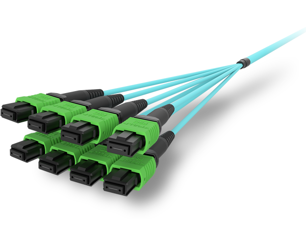
- 📡 MPO / MTP High-Density Cabling — 12 / 24 / 32-fiber for high-density data centers
- ⚡ AOC & DAC Cables — short-reach GPU interconnects, OEM compatible
- 🧩 SFP / SFP+ / SFP28 / QSFP28 Modules — 1G to 100G optical transceivers
- 📋 Data Center Cabling Solutions — end-to-end design guide
- ❓ Read our FAQ — compatibility, polarity, lead time, MOQ
💬 Get a quote in 12 hours: Contact Candy · WhatsApp +86 188 1445 5697 · candy@abptel.com