
High-speed optical networks are the backbone of modern data centers, AI infrastructure, and telecom systems. As demands for higher bandwidth and lower latency increase, mitigating link failures becomes essential to preserving network reliability and preventing costly disruptions. Link failures can stem from a variety of causes, including physical layer impairments, component malfunctions, poor design choices, operational factors, and even economic or geopolitical challenges. This article systematically explores these causes, offering data center network engineers, IT managers, and system integrators actionable insights to optimize network architecture and prevent outages. From fiber degradation to amplifier inefficiencies, each chapter sheds light on a critical aspect of link failure, enabling stakeholders to address these issues comprehensively and maintain robust optical networks.
Where Link Failures Begin: Physical-Layer Impairments and Fiber Infrastructure Weak Points in High-Speed Optical Networks

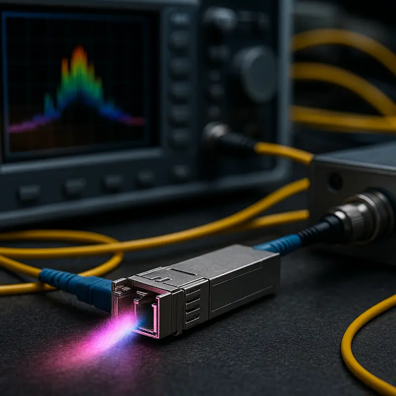
At high data rates, many link failures start long before traffic reaches switching logic or software controls. They begin in the optical path itself, where tiny losses, reflections, timing distortions, and mechanical defects can push a link beyond its operating margin. A circuit may appear healthy during light-load periods, then show burst errors, flapping, or complete loss of signal when temperature shifts, patching changes, or channel speeds rise. That is why physical-layer analysis remains central to understanding what causes link failures in high-speed optical networks.
The most common trigger is simple attenuation, but the cause is rarely simple. Every connector, splice, bend, and patch point consumes part of the loss budget. At lower rates, a network may tolerate this gradual erosion. At higher rates, the same path can fail because receiver sensitivity margins shrink and signal quality requirements tighten. Dirty end faces are especially deceptive. A single contaminated connector can add insertion loss and back reflection at once, creating intermittent faults that resemble equipment instability. Excessive bend radius, poor cable routing, and hidden stress in trunks or jumpers can produce similar symptoms, especially after moves or maintenance.
Reflection and dispersion also become more destructive as speed increases. Return loss from damaged or mismatched interfaces can disturb transmitter operation and degrade the eye opening at the receiver. Chromatic dispersion spreads pulses over distance, while polarization effects cause uneven delay that changes with temperature and fiber movement. In dense, longer-reach systems, nonlinear effects can further distort channels when optical power is too high. None of these impairments needs to be catastrophic on its own. Link failure often occurs when several small penalties stack together and erase the remaining margin.
Infrastructure age and installation quality matter just as much as optical theory. Legacy fiber plants may contain undocumented splices, mixed fiber grades, poor patch discipline, or connector wear that was acceptable for earlier generations. Outdoor segments add moisture ingress, thermal cycling, vibration, and sheath damage. Even in controlled facilities, polarity mistakes, overloaded pathways, and unmanaged patch fields can create failures that seem random until the physical path is audited. For teams validating suspected plant issues, tools such as an optical time-domain reflectometer help expose localized loss events, reflections, and distance-to-fault patterns that power readings alone can miss.
This is why stable high-speed operation depends on more than nominal reach. It depends on a clean, well-characterized channel with enough margin to absorb normal variation. Once the fiber path is compromised, the components attached to it face harsher conditions, which is where transceiver and amplification-related failures become far more likely.
How Optical Components, Transceivers, and Amplifiers Trigger Link Failures in High-Speed Optical Networks
If fiber impairments explain why light degrades in transit, component-level faults explain why a link fails even when the path itself looks acceptable. In high-speed optical networks, transceivers, passive optical parts, and amplification stages often sit at the center of intermittent alarms, rising bit errors, and outright loss of signal. These failures are especially common as data rates climb, margins shrink, and operators mix optics from different vendors or generations.
Transceivers are usually the first place engineers look, and for good reason. A link can fail when a module’s transmit power drifts, receiver sensitivity falls, or internal lasers age unevenly. Thermal stress is a frequent trigger. As case temperatures rise, optical output, wavelength stability, and error performance can shift enough to push a previously healthy link beyond tolerance. At lower speeds, a network might absorb that drift. At 400G or 800G, it often cannot. Compatibility problems make this worse. Even when two modules share a form factor, they may differ in firmware behavior, digital diagnostics, lane mapping, or supported signaling assumptions. That is why careful attention to reducing compatibility risks with optical modules matters before deployment, not after failures appear in production.
Passive optical components can be just as disruptive. Splitters, mux-demux units, filters, and patch interfaces introduce insertion loss, reflection, and wavelength-dependent behavior that may remain hidden until traffic increases or a span is upgraded. In dense systems, small filter misalignment can clip signal edges or reduce channel isolation. Dirty or damaged mating surfaces inside component chains add another layer of loss that is hard to isolate because no single point looks catastrophic. Instead, the network shows unstable margins, bursty frame loss, or links that fail only under heat, load, or specific wavelength plans.
Amplifiers create a different class of failure. They are designed to extend reach, but they can also amplify noise, distort channel balance, and mask underlying faults. If gain is set too high, the receiver can overload. If gain is too low, the link can fall below sensitivity. Uneven gain across wavelengths can quietly punish some channels while others appear normal. Amplified spontaneous emission further reduces optical signal quality, especially over long cascades. A failing pump laser, degraded control loop, or poor gain equalization may not drop the span immediately. Instead, it narrows operating margin until routine variation causes service-impacting errors.
What makes these failures difficult is their tendency to interact. A slightly weak transmitter, a marginal filter, and a noisy amplifier may each pass acceptance testing alone. Together, they can create a fragile link that breaks under ordinary operating conditions. That is why component health, interoperability discipline, and optical margin analysis are essential bridges between raw fiber physics and the broader design and control decisions that determine overall network resilience.
How Network Design and Control-Plane Decisions Trigger Link Failures in High-Speed Optical Networks
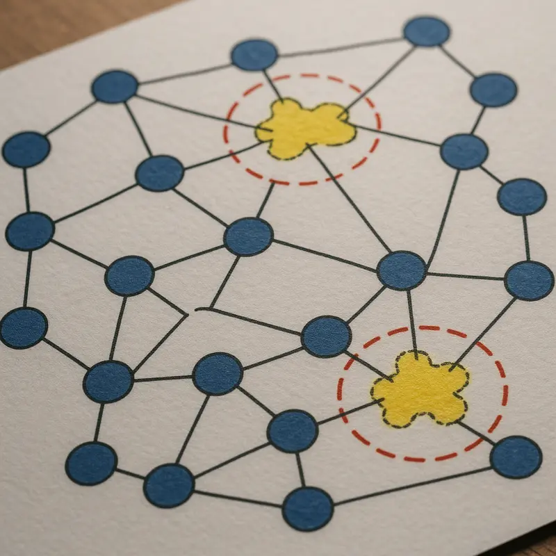
Many high-speed optical link failures are not born in the fiber or optics at all. They begin in architecture choices, protocol behavior, and management logic that push a healthy physical link into an unstable state. As data rates rise, design margins shrink. That makes weak planning at the network and control layers far more visible.
A common cause is mismatched network design assumptions. Engineers may build for nominal traffic, then run the network under bursty east-west flows, fast failover events, or rapid scaling. Oversubscription can magnify microbursts and congestion. Those conditions do not damage light transmission directly, but they can trigger packet loss, retransmissions, route churn, and interface flaps that operators may first interpret as an optical fault. The same happens when latency-sensitive services share paths with heavy replication traffic. At high speeds, small design errors create large operational instability.
Protocol choices also matter. Link aggregation, routing timers, forward error correction settings, and auto-negotiation behavior must align across the path. If they do not, links may oscillate between up and down states, remain technically active but unusable, or produce intermittent errors during traffic transitions. Some failures appear only during reconvergence. A path can pass lab validation, then collapse when routing updates, protection switching, and load balancing interact under stress. This is especially common during large bandwidth transitions, where planning mistakes in breakout schemes, lane mapping, and migration sequencing can compound risk, as seen in 400G and 800G migration pitfalls.
The control plane can also create failure conditions through instability rather than outright misconfiguration. Aggressive timers may cause unnecessary failovers. Uneven metric policies can produce route flapping. Protection mechanisms may compete, with one layer restoring traffic while another simultaneously reroutes it. In optical networks, that interaction can generate transient overloads, out-of-order traffic, or repeated switching events that look like defective links. Software defects and inconsistent firmware behavior across nodes can intensify the problem.
The management plane adds another layer of risk. Poor inventory accuracy, stale topology data, and incorrect templates often lead to provisioning errors. A link may be assigned the wrong policy, the wrong monitoring threshold, or the wrong service profile. Telemetry can also mislead. If alarms are too sensitive, operators chase noise. If thresholds are too loose, early warning signs are missed. Automation helps at scale, but weak guardrails can spread configuration mistakes across many links in seconds.
These causes sit between physical defects and environmental disruptions. They show that a link can fail because the network tells it to behave in ways its design, protocols, or operational logic cannot sustain.
How Environmental Stress, Daily Operations, and Maintenance Mistakes Trigger Optical Link Failures
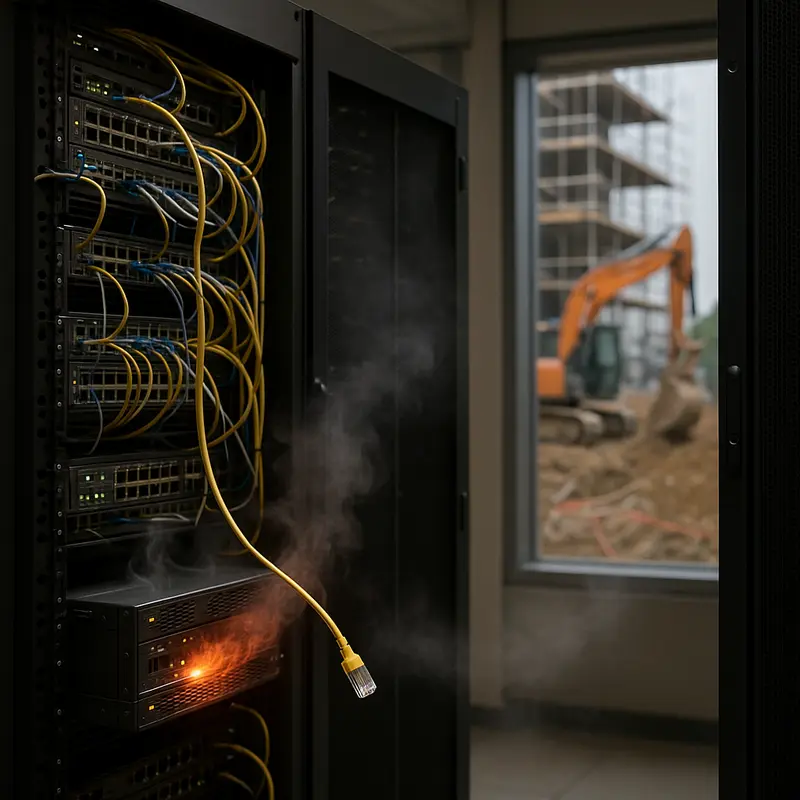
After control-plane and design issues are accounted for, many high-speed optical failures still begin in the physical world. Fiber links are sensitive to heat, dust, moisture, vibration, and mechanical strain. At lower rates, a link may tolerate small defects for months. At high speeds, the same defects can push insertion loss, reflectance, or signal integrity beyond the safe margin. The result is not always a hard outage. More often, operators see rising error counts, unstable performance, and intermittent failures that appear random until the environmental pattern becomes clear.
Temperature is one of the most common triggers. Optical components drift as they heat and cool. Fiber attenuation can change slightly, but connectors, splices, and enclosures often create the bigger problem. A connection that was acceptable in a cool rack can become marginal in a hot aisle or outdoor cabinet. Moisture adds another layer of risk. Water ingress can degrade cable materials, contaminate interfaces, and worsen microbending. In outside plant environments, wind, ice, and repeated thermal cycling can slowly alter cable geometry and tension. Even in controlled facilities, vibration from fans, nearby machinery, or repeated cable movement can disturb poorly secured connections.
Operations teams also create failures unintentionally. High-density deployments leave little room for careless routing. Tight bend radius, cable compression under trays, and overpacked pathways introduce macrobending loss that may only appear after a later move or temperature shift. Mixed patching practices can leave end faces exposed long enough to collect dust, oil, or residue from improper cleaning. At 400G and above, contamination that once seemed minor can become a major source of loss and reflection. This is why disciplined inspection and cleaning matter, especially in parallel-fiber systems where one dirty interface can affect an entire channel. The practical risks are similar to those described in this guide to 400G/800G MPO/MTP loss budget and polarity pitfalls.
Maintenance windows are another common origin point. Many link failures are introduced during routine work, not emergency events. A technician may reseat a connector without inspecting it, mislabel a jumper, exceed pull tension during replacement, or leave a panel partially latched. Seemingly small handling errors can change optical loss enough to break a tight budget. Deferred maintenance is just as dangerous. Dirty panels, aging seals, undocumented patch changes, and unmanaged cable stress accumulate until a later upgrade exposes the weakness.
These disruptions sit between engineering intent and real-world reliability. A network may be well designed and logically sound, yet still fail because daily conditions erode physical margin faster than teams detect it. That makes environmental control, handling discipline, and maintenance quality central causes of link failure, not secondary concerns.
How Economics, Politics, and Public Risk Quietly Shape Link Failures in High-Speed Optical Networks

Technical faults rarely explain the full pattern of link failures in high-speed optical networks. After environmental stress and maintenance mistakes are accounted for, reliability is still shaped by decisions made far from the rack, conduit, or splice tray. Budget pressure, trade policy, labor conditions, permitting delays, and public safety exposure all influence whether a link remains stable over its service life.
Cost control is often the first hidden driver. Operators may postpone route diversity, reduce spare inventory, delay fiber characterization, or compress acceptance testing to meet deployment targets. None of those choices creates an immediate outage. They do, however, narrow the margin for recovery when attenuation rises, connectors degrade, or a single civil cut removes the only viable path. Economic pressure can also push networks toward mixed generations of optics and infrastructure, increasing interoperability uncertainty during upgrades. That is especially relevant in faster migrations, where link budgets tighten and tolerance for small design errors falls. Planning discipline matters as much as component performance, which is why careful transition strategy in guides on migrating from 100G to 400G is closely tied to reliability, not just capacity.
Geopolitical forces add another layer. Trade restrictions, export controls, customs delays, and sanctions can interrupt the supply of optics, fiber, test instruments, and repair parts. When replacement lead times stretch, operators may keep aging links in service longer than intended or substitute parts that have not been fully validated in the target environment. Large networks can absorb some of that strain through qualification programs and multisource procurement. Smaller operators often cannot. The result is an uneven reliability landscape where the same fault condition is resolved quickly in one region and persists for weeks in another.
Physical infrastructure is also exposed to social and political realities on the ground. Permitting disputes can block diverse routing and force cables into congested corridors. Theft, vandalism, sabotage, and accidental damage from poorly coordinated construction all increase where governance is weak or infrastructure mapping is fragmented. In some areas, unrest or conflict limits technician access, turning a minor impairment into a prolonged outage. Public policy therefore affects failure duration as much as failure frequency.
Societal dependence on optical links raises the stakes further. Hospitals, emergency services, financial systems, cloud platforms, and mobile backhaul all rely on low-latency, high-availability transport. As dependence grows, the cost of even brief disruption becomes broader than lost packets or service credits. Reliability planning must therefore consider resilience as a civic requirement, not only an engineering target. High-speed optical networks fail for physical reasons, but their vulnerability is often created upstream by procurement choices, policy constraints, and the social systems built on top of them.
Final thoughts
High-speed optical networks are pivotal for today’s digital economy, but link failures can compromise their reliability and efficiency. By addressing physical layer issues, optimizing component performance, improving network design, minimizing environmental disruptions, and accounting for societal pressures, engineers and planners can create resilient systems capable of meeting current and future demands. Proactive identification of these risks not only safeguards infrastructure but also ensures seamless data transmission across critical applications. Given the complexity of these challenges, understanding their multifaceted causes is critical for preventing outages and maintaining operational excellence.
Talk to ABPTEL about high-speed optics, MTP/MPO cabling, and data center interconnect solutions to future-proof your network.
Learn more: https://abptel.com/contact/
About us
ABPTEL offers high-speed optical transceivers, MTP/MPO cabling systems, DAC and AOC cables, PoE switches, FTTA solutions, and fiber tools tailored for data center, AI, telecom, and network infrastructure needs. Partner with us for industry-leading solutions to enhance network performance and reliability.