Sourcing high-speed optical modules for modern network architectures, including data centers and AI environments, comes with inherent risks related to compatibility and performance. Engineers, planners, and procurement teams must navigate issues like standards mismatches, vendor coding, fiber plant discrepancies, thermal constraints, and firmware interdependencies. Each of these aspects directly impacts reliability and efficiency, making systematic preparation and validation essential. This article outlines five focused strategies to address these challenges: aligning standards and interfaces; tackling vendor coding and management protocols; optimizing optical link budgets; mitigating thermal and mechanical issues; and incorporating supply chain planning. These pillars empower organizations to deploy high-speed optics confidently, ensuring network stability and scalability.
Getting Standards and Interfaces Right Before High-Speed Optical Module Compatibility Breaks Down
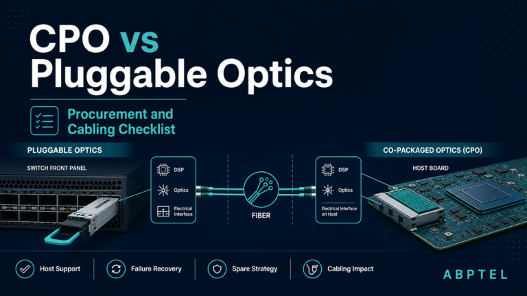
Reducing compatibility risk begins long before a module is inserted into a switch or server. It starts with strict alignment between the host port, the pluggable form factor, and the standards that define how electrical signals, optical lanes, and management behavior are supposed to work together. Many sourcing mistakes happen because buyers treat a speed label such as 100G, 400G, or 800G as the main requirement. In practice, that label is only the surface. The real determinant of success is whether the module matches the exact PMD, lane architecture, signaling method, and management interface expected by the host.
A reliable sourcing process therefore has to anchor on IEEE and MSA definitions, not just on nominal data rate. A 400G port, for example, may expect DR4, FR4, or LR4 behavior, and those are not interchangeable. They differ in wavelength plan, reach, connector style, and fiber assumptions. The same applies at lower speeds. A 25G port may look physically similar to 10G, but the electrical performance, host tuning, and management expectations are different, as seen in this comparison of 25G SFP28 vs 10G SFP+. If the selected module does not align to the host’s intended PMD and lane model, link bring-up may fail outright, or worse, appear stable while operating with weak margin.
Interface alignment also means matching the host’s signaling and error-correction assumptions. NRZ and PAM4 are not minor variations. They impose different channel budgets, different noise tolerance, and different FEC requirements. A module designed around PAM4 lanes usually depends on the host supporting the proper Reed-Solomon FEC mode. If the host uses a different FEC profile, disables it, or applies an unsupported breakout mapping, the result can be persistent errors, unstable training, or no link at all. This is especially important in 200G, 400G, and 800G deployments, where gearbox behavior, lane distribution, and compliance margins become much tighter.
Management compatibility is just as important as optical and electrical fit. SFP-based modules typically rely on SFF-8472 behavior, while newer QSFP-DD and OSFP devices depend on CMIS for application advertisement, alarms, low-power handling, and state transitions. If the host expects one memory model or one CMIS revision and the module presents another, visibility and control can degrade even when light levels are fine. That often shows up as missing telemetry, broken alarms, failed low-power exit, or inconsistent hot-swap behavior.
The safest approach is to treat standards alignment as a sourcing gate. Verify the exact form factor, PMD, lane signaling, FEC dependency, connector type, and management specification before price or lead time enters the decision. That discipline prevents many downstream issues that are often misdiagnosed as firmware or coding problems.
Controlling Coding, CMIS/SFF Behavior, and Firmware Drift to Reduce Optical Module Compatibility Risk

After standards and host interface alignment are confirmed, many compatibility failures still appear at a more practical layer: the module is electrically correct, yet the host refuses it, misreads it, or manages it inconsistently. This is where vendor coding, CMIS or SFF compliance, and firmware discipline become decisive. In sourcing, these factors often separate optics that merely fit from optics that operate reliably across deployment, upgrades, and replacements.
Vendor coding remains one of the most common causes of avoidable rejection. Many hosts inspect EEPROM fields such as vendor name, identifier, part number, checksum, and related profile data before enabling the port fully. A module may link physically, yet still lose digital diagnostics, alarms, or official support if its coding does not match platform expectations. That is why procurement teams should treat coding as a controlled requirement, not an afterthought. Every purchase order should specify host platform, software version, and required coding profile. This becomes even more important when qualifying alternate suppliers or planning spares for mixed environments. A broader sourcing strategy, such as the one outlined in this 400G transceiver procurement guide, helps prevent mismatches before modules ever reach the rack.
Management compliance matters just as much. SFP-class modules depend on SFF memory structures and diagnostics behavior, while newer high-speed form factors rely heavily on CMIS for application advertisement, low-power transitions, interrupts, alarms, and state control. Small deviations can create large operational problems. A host may fail to read thresholds correctly, mishandle low-power mode, or stall during initialization if the module does not follow expected timing or page structure. For that reason, compatibility reviews should verify more than the presence of DOM fields. They should confirm alarm behavior, reset handling, interrupt signaling, application selection, and state-machine transitions under hot-swap and reboot conditions.
Firmware adds another layer of risk because compatibility is not static. A known-good module can become problematic after a network operating system update, a supplier component change, or a quiet firmware revision within the same part number. This is how compatibility drift enters production. The safest approach is to maintain a living matrix that ties module part number, firmware revision, coding profile, and host software release together. Lock those combinations once validated. Any update should move through controlled regression testing, including recognition, telemetry accuracy, link stability, and recovery after resets.
This discipline also strengthens supply chain resilience. It reduces surprise failures during replenishment, keeps second-source options realistic, and ensures that the next chapter’s optical budget work is not undermined by a module the host cannot properly identify or manage.
Reducing Compatibility Risk Through Precise Optical Link Budgeting and Fiber Plant Matching
A large share of optical module compatibility problems starts outside the transceiver itself. A module can be correctly coded, standards-compliant, and fully recognized by the host, yet still fail in production because the optical path does not match the selected PMD. That is why link budgeting and fiber plant validation sit at the center of low-risk sourcing.
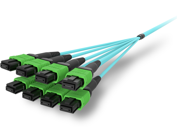
The first check is simple but often skipped: match the optic type to the real cabling environment, not the port speed alone. SR optics belong on multimode fiber, while DR, FR, and LR are designed for single-mode fiber. Parallel optics such as DR4 and SR8 also require the correct MPO fiber count, polarity, and patching scheme. Duplex modules need LC infrastructure. Ordering the wrong optic for the installed plant creates a compatibility issue that no firmware update can solve.
Reach labels also need careful interpretation. A 2 km FR module does not guarantee 2 km in every network. Actual performance depends on total insertion loss across jumpers, trunks, cassettes, splices, and patch panels. Every connection consumes margin. Dirty endfaces consume even more. With PAM4 optics, that margin is tighter than many buyers expect, because receiver sensitivity, TDECQ, and connector loss interact more sharply than in older NRZ links. A link that looks acceptable on paper can become unstable after a single contaminated patch cord or an extra cross-connect.
This is why sourcing teams should ask for more than a datasheet reach claim. They should verify wavelength plan, connector type, supported fiber class, minimum and maximum loss assumptions, and whether the module is intended for duplex or parallel single-mode paths. For higher-speed deployments, especially 400G and above, it also helps to align transceiver selection with structured guidance such as this 400G DR4, FR4, and LR4 transceiver overview, because the physical media options differ in cost, cabling impact, and operational risk.
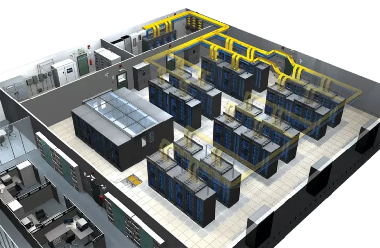
Fiber plant condition matters as much as transceiver selection. Legacy trunks may have poor polarity records, hidden attenuation, or mixed connector grades. Some facilities carry both multimode and single-mode jumpers in the same pathways, which increases the chance of installation errors. Before qualifying optics, teams should inspect and clean connectors, measure end-to-end loss, confirm polarity, and compare the worst-case path against the module’s published budget. OTDR traces and insertion-loss reports are far more valuable than assumptions.
This discipline becomes even more important before moving into thermal and signal integrity validation. If the optical path is misaligned from the start, later testing can misdiagnose the root cause. Clean budgeting and accurate fiber matching remove that uncertainty and prevent expensive compatibility surprises after deployment.
Reducing Compatibility Risk Through Thermal Headroom, Mechanical Fit, and Clean Signal Paths
After the fiber type and loss budget are validated, many compatibility failures still appear at the physical interface between the module and the host. A transceiver can match the target reach on paper and still fail in production because the chassis cannot cool it, the cage does not support its power class, or the electrical channel cannot maintain margin at the required lane speed. This is why thermal, mechanical, and signal integrity checks should be treated as core sourcing criteria, not late-stage installation details.
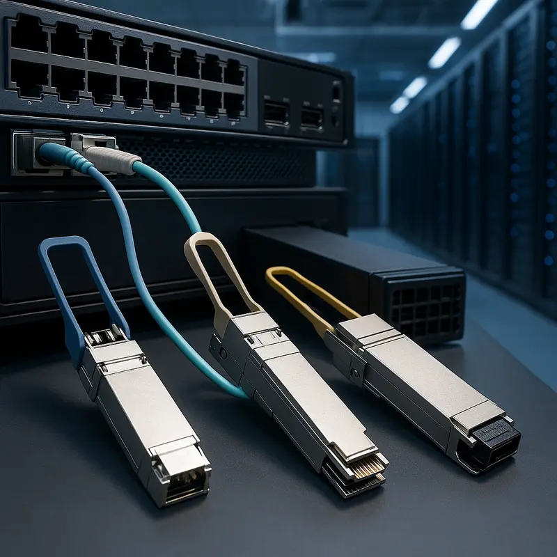
Mechanical compatibility starts with the obvious, but often overlooked, point that high-speed form factors are not interchangeable. A module may share a similar purpose with another pluggable, yet still be unusable because the cage, connector geometry, latch design, or front-panel spacing differs. Even when the module fits the port family, heatsink height and riding heatsink clearance can create insertion or ejection problems. Dense faceplates make this more critical, especially as power rises from earlier generations into 400G and 800G platforms. Teams planning these higher-density upgrades should align optics selection with chassis design and airflow assumptions early, particularly for 400G vs 800G transceiver decisions.
Thermal behavior is just as important. High-speed PAM4 optics run with tighter margins and higher power draw than older NRZ modules. If the host airflow direction, cage design, or thermal dissipation path is mismatched, the module may operate normally in the lab and then throttle, flap, or age prematurely in a warmer rack. Compatibility risk increases when buyers select modules close to the chassis power or cooling limit, because a small shift in ambient temperature or port utilization can push the module outside its stable range. The safer sourcing approach is to preserve thermal headroom, verify supported module power classes, and test at hot and cold corners rather than relying on room-temperature bring-up.
Signal integrity adds a third layer of risk. At 25G NRZ, some hosts can tolerate modest channel weakness. At 50G and 100G per lane PAM4, the same weakness can become a hard interoperability problem. Host board insertion loss, connector quality, crosstalk, retimer behavior, and lane mapping all affect whether the module can maintain acceptable pre-FEC error rates. A module that is standards-compliant in isolation may still struggle in a host with limited channel margin. This is especially true in breakout modes, where gearbox assumptions and lane assignments must line up exactly.
For sourcing teams, the practical lesson is clear: ask for more than a data sheet. Require host-specific validation, confirm thermal and power-class support, and review compliance evidence for the actual electrical interface. When physical fit, cooling capacity, and channel margin are verified together, compatibility risk drops sharply before the optics ever reach production.
Planning Beyond Price: Supply Chain, Cost, and Compliance Moves That Reduce Optical Module Compatibility Risk

Compatibility risk does not end with technical fit. It often enters through procurement decisions, supplier changes, and policy gaps that seem harmless at purchase time. A module may match the port on paper, yet fail later because a new lot uses different firmware, a substitute component shifts behavior, or a rushed buy arrives with the wrong host coding. That is why sourcing discipline matters as much as lab validation.
The safest buying strategy treats optical modules as controlled infrastructure, not interchangeable commodities. Start by defining approved part numbers by host platform, firmware baseline, coding profile, and intended reach. Then qualify at least two sources for each critical optic type. Dual sourcing reduces shortage risk, but only if both sources are validated to the same standard. If one supplier ships a slightly different memory map, alarm threshold set, or CMIS implementation, your “backup” source can become a new compatibility event. A living compatibility matrix should therefore sit beside the approved vendor list, linking module revision, lot code, and operating software version.
Economics should also be evaluated through total cost of ownership, not unit price alone. Lower-cost optics can be reasonable, but only if the savings survive added test time, higher rejection rates, operational troubleshooting, and slower RMAs. This becomes more important at 400G and 800G, where tighter margins make substitution risk more expensive. Teams planning larger rollouts can use a structured 400G transceiver procurement guide mindset to compare not just pricing, but qualification evidence, supply continuity, and long-term support. Lead times matter here as well. When DSPs, lasers, or subassemblies tighten in supply, vendors may introduce alternate bills of materials. Without change-control requirements, those substitutions can quietly alter interoperability.
Regulatory and procurement constraints add another layer. Public-sector, defense, and multinational deployments may need proof of origin, traceability, trade compliance, or restricted-vendor screening. In some environments, failing these checks can force a last-minute vendor swap, which is exactly when compatibility mistakes happen. Require documentation early: country of origin, environmental compliance, safety certifications, lot traceability, and, where relevant, export classification. For higher-assurance networks, insist on authorized channels, anti-counterfeit controls, and firmware authenticity measures. Counterfeit or gray-market modules are not just a warranty problem; they can carry inconsistent EEPROM data, poor calibration, and unpredictable thermal behavior.
Good planning turns procurement into a compatibility safeguard. When sourcing rules, validation records, compliance documents, and lifecycle tracking are managed together, organizations reduce both technical surprises and business disruption. That discipline is what keeps a qualified optical design from being undermined by the next purchase order.
Final thoughts
Reducing compatibility risks when sourcing high-speed optical modules requires strategic alignment of standards, coding, fiber planning, and supply chain integrity. Tailored validation processes further ensure mechanical, thermal, and signal compatibility. By integrating these practices, network architects and engineers can achieve reliable and scalable connectivity across critical systems. Whether for data centers or AI infrastructures, adopting a proactive framework minimizes disruptions and safeguards operational continuity.
Contact ABPTEL for tailored solutions in high-speed optics, cabling, and full-stack connectivity management.
Learn more: https://abptel.com/contact/
About us
ABPTEL delivers advanced network solutions, including high-speed transceivers, MTP/MPO cabling systems, DAC/AOC cables, PoE switches, FTTA setups, and a full suite of fiber toolkits. Designed for data centers, AI infrastructures, telecommunications, and enterprise networks, our offerings prioritize reliability, performance, and scalability to meet today’s connectivity demands.
Talk to ABPTEL
Looking for the right optical hardware for your AI data center, GPU cluster, or FTTA project? ABPTEL ships from Shenzhen with OEM/ODM support, fast lead times, and engineering-level pre-sales advice.
- 🔥 400G & 800G OSFP / QSFP-DD Transceivers — for AI training fabrics and hyperscale spine-leaf
- 📡 MPO / MTP High-Density Cabling — 12 / 24 / 32-fiber for high-density data centers
- ⚡ AOC & DAC Cables — short-reach GPU interconnects, OEM compatible
- 🧩 SFP / SFP+ / SFP28 / QSFP28 Modules — 1G to 100G optical transceivers
- 📋 Data Center Cabling Solutions — end-to-end design guide
- ❓ Read our FAQ — compatibility, polarity, lead time, MOQ
💬 Get a quote in 12 hours: Contact Candy · WhatsApp +86 188 1445 5697 · candy@abptel.com