OPGW Cable Selection Guide: Why “Off-the-Shelf” Specs Fail on Transmission Lines
For power design institutes & EPC managers · By Candy @ ABPTEL
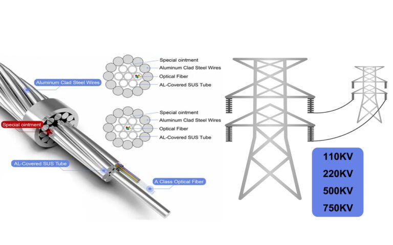
Unlike standard fiber cables, OPGW (Optical Ground Wire) is not a commodity. It is a shield wire that must survive two enemies at the same time:
Mechanical Stress (ice/wind) and Electrical Heat (short-circuit & lightning).
We often receive RFQs asking for a “standard 24-core OPGW price.”
Our answer is always: “Please share your tower and short-circuit data first.”
Choosing the wrong structure—like using a heavy stranded OPGW on an old 110 kV tower—can exceed the tower’s wind/ice allowance.
Ignoring the kA²·s requirement can push the fiber coating above 200 °C during faults, melting fibers.
Below is ABPTEL’s engineer guide to match the right OPGW to your grid—you must calculate, not guess.
Quick Structure Selection (At a Glance)
| Scenario | Recommended OPGW | Key Reason | Typical Fiber Count | Notes |
|---|---|---|---|---|
| Retrofit on old lines (110–220 kV), tight tower load | Central Stainless-Steel Tube OPGW | Smaller diameter & weight → lower wind/ice load | 24–48F | Matches original sag-tension; easier construction |
| New main corridors (220–500 kV), high capacity | Multi-Tube Stranded OPGW (Double-Layer Armor) | More tubes → high fiber count & higher RTS | 96–144F | Better heat dissipation for long spans |
| High thunder density / high short-circuit energy | High Short-Circuit OPGW (Lightning-Resistant) | Aluminum-alloy outer wires ↑ conductivity → less thermal rise | 24–72F | Designed by kA²·s verification (1–3 s faults) |
Scenario 1: Retrofitting Old Lines (The Weight Problem)
When upgrading an existing line (replacing galvanized earth wire with OPGW), the #1 constraint is Tower Load.
Old towers were not designed for heavy stranded OPGW. Extra wind/ice load can exceed safety margins and change sag-tension behavior.
Choose the Central Stainless-Steel Tube OPGW.
- Smaller Diameter → lower wind pressure coefficients.
- Lighter → closer to original earth-wire RTS & sag.
- 24–48F → enough for substation/tele-protection rings.
Scenario 2: New UHV Corridors (The Capacity Problem)
On new 220–500 kV corridors, priorities shift to fiber count, heat capacity and RTS. Central tubes cap out in fiber volume.
✅ Solution: Stranded OPGW
Use Multi-Tube Stranded OPGW (double-layer armor). Stranding multiple stainless-steel tubes delivers 96–144F with robust tensile performance for long spans and heavy icing zones.
Scenario 3: Lightning Zones (The Heat Problem)
The most overlooked parameter is Short-Circuit Energy, often expressed as kA²·s.
When a fault or lightning occurs, OPGW conducts current to ground. Instant Joule heating can raise temperature above 200 °C, degrading fiber coating if conductivity is insufficient.
✅ Solution: High Short-Circuit OPGW with Aluminum-Alloy (AA) outer wires.
AA offers ~3× the conductivity of steel, dispersing heat faster and protecting fibers during 1–3 s faults.
Thermal Check: The One Number You Must Verify
Utilities typically provide fault current and clearing time (e.g., 32 kA for 1 s). Your OPGW must pass the specified
I²·t (kA²·s) without exceeding the allowable temperature rise. Ask for a short-circuit verification sheet during design review.
Don’t Guess Your Specs. Calculate Them.
To issue a valid quote and thermal check, our engineers need:
- Voltage level (kV) & corridor type (new / retrofit)
- Short-circuit current & clearing time (e.g., 31.5 kA · 1 s → 992 kA²·s)
- Required RTS (kN), span length, wind/ice region
- Existing earth-wire data (for retrofit): diameter, mass, sag-tension curve
- Fiber count & routing plan (24F / 48F / 96F / 144F)
We will return a structure proposal (Central Tube / Stranded / High Short-Circuit), thermal verification, and a bill of materials.
Common Pitfalls We See on OPGW Projects
- Ordering “standard 24F” without kA²·s data → fibers damaged after first thunder season
- Picking stranded OPGW for a fragile retrofit tower → wind/ice overload risk
- Ignoring RTS vs. span / ice region → excessive sag or construction failure
- No thermal verification sheet in the submittal package → approval delays
Explore OPGW Options
• Retrofit / light load → Central Tube OPGW
• High capacity corridors → Stranded OPGW
• Lightning / high fault energy → High Short-Circuit OPGW
• More resources → OPGW Category
We validate RTS, kA²·s and sag, then return a stamped datasheet for approval.
OPGW FAQs (Engineers’ Edition)
How do I compare Central Tube vs. Stranded?
Stranded = multi-tube high capacity (96–144F) with higher RTS → better for new long-span corridors.
What is kA²·s and why does it matter?
What data do you need for a formal design?
Can ADSS replace OPGW?