
Description
Why “High Short-Circuit Capacity” OPGW is a distinct product class
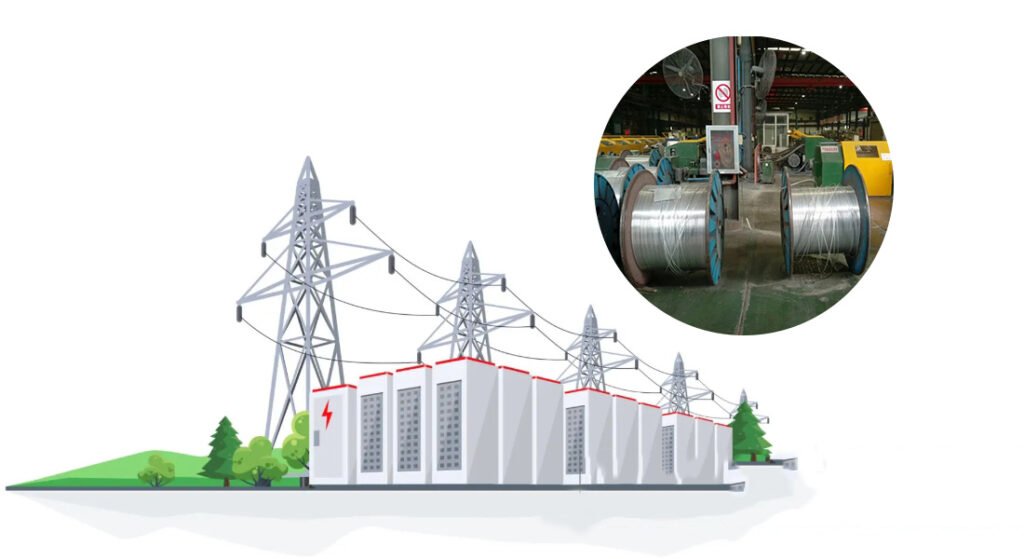
In real power-grid projects, OPGW is not purchased like telecom cable. It is a grid safety component. Beyond carrying fibers for SCADA, protection relays, and monitoring, OPGW must function as an overhead ground wire that:
- Shields conductors from lightning, and
- Conducts short-circuit current during fault events.
When fault current is high (or fault duration is longer), thermal duty becomes a primary risk. Overheating can degrade mechanical strength over time and jeopardize the optical unit. That’s why many utilities specify OPGW by kA²s (short-circuit capacity) in addition to mechanical criteria such as RTS and MAT.
What is kA²s and how it affects the cable design
kA²s is the short-circuit thermal duty index used in OPGW selection. It correlates to how much energy the ground wire must safely carry during a fault event. Higher kA²s generally requires:
- higher effective conductive cross-section,
- improved thermal mass and heat dissipation,
- optimized ACS/AA wire ratios and layer geometry.
ABPTEL engineering approach
ABPTEL designs High Short-Circuit OPGW around four procurement-critical parameters:
- Short-Circuit Capacity (kA²s) — per utility fault study
- RTS (Rated Tensile Strength) — per ruling span and climate load
- MAT (Max Allowable Tension) — typically set around the safe installation/operating range (commonly ≈40% of RTS, but determined by sag-tension rules)
- Span / Ruling Span — section-by-section mechanical constraint
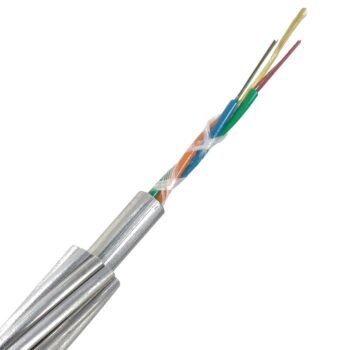
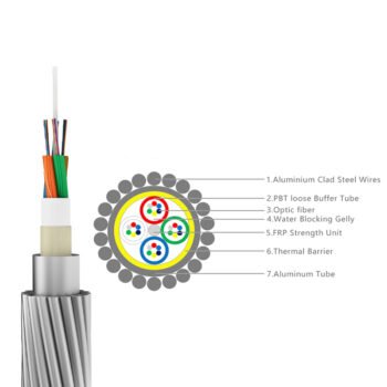
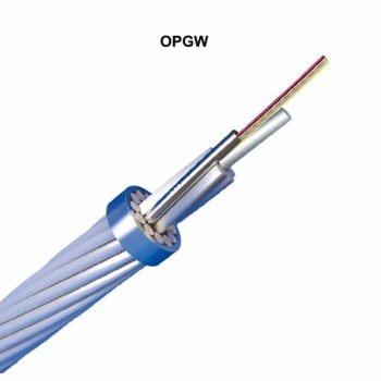
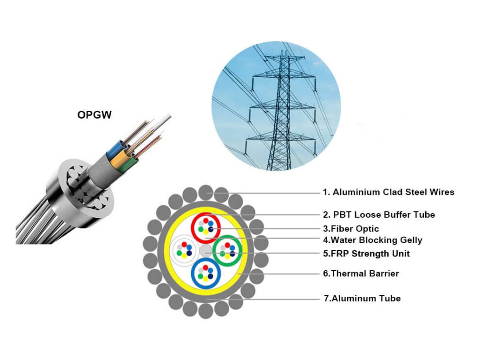
The optical unit is protected inside sealed stainless steel tube(s) filled with water-blocking compound, while the outer layers of ACS/AA conductive wires deliver current-carrying capability and lightning performance.
Typical deployment scenarios
- Substation entrance/exit spans where short-circuit duty is often higher
- Heavy lightning regions requiring robust shielding performance
- Main corridor segments with stricter thermal and mechanical margins
- New 220kV/500kV builds where both kA²s and RTS are explicitly specified in tender docs
Specifications
A) Must-Fill Attributes
| Attribute | ABPTEL Offering | Notes |
|---|---|---|
| Short-Circuit Capacity (kA²s) | Customized (project-specific) | Define by fault current magnitude and duration |
| RTS (Rated Tensile Strength) | Customized (project-specific) | Determined by ruling span + wind/ice + safety margin |
| MAT (Max Allowable Tension) | Typically ≈40% of RTS (customized) | Final MAT follows sag-tension engineering rules |
| Span (m) | Customized by section | Use ruling span; not a fixed “one-size” number |
| Fiber Count | 24–144 fibers (custom) | Based on comm network plan |
| Optical Unit | Sealed stainless steel tube(s), gel-filled | Water-blocking + mechanical protection |
| Conductive Wires | ACS + AA (design optimized) | Balances conductivity and strength |
| Structure | Central tube or stranded multi-tube (project) | High kA²s designs often use robust outer layers |
| Operating Temperature | Typical -40°C to +70°C (project) | Confirm per tender spec |
| Standards (Reference) | IEEE 1138 / IEC (as required) | Provide compliance statement with order |
B) Reference Range
Use this snippet on the page to keep EEAT strong:
Typical engineering ranges (reference only):
- kA²s: commonly engineered in the 80–300 kA²s class for demanding sections (higher available by design)
- RTS: typically engineered in the 60–160 kN class for mainstream projects (higher available by design)
- Final values depend on tower design, ruling span, climate load, and fault study.
If you have your own factory “standard designs,” replace this reference range with your real OD/weight/RTS/kA²s tables for even stronger trust.
Key Benefits
- High kA²s design headroom for severe fault-current duty
- Lightning shielding + fiber communication in one integrated overhead ground wire
- Sealed stainless tube optical protection improves fiber survivability over long service life
- Optimized ACS/AA architecture balances conductivity, thermal behavior, and tensile strength
- Engineering support for tender compliance: kA²s / RTS / MAT / ruling span inputs and documentation package
Applications
- Substation entry/exit sections
- Heavy lightning corridors
- High fault-current duty lines
- 220kV / 500kV transmission routes requiring explicit kA²s specification
- Grid monitoring, SCADA, teleprotection and operational communications
Documentation & Quality
ABPTEL can provide (on request):
- Datasheet and engineered configuration proposal
- Compliance statement to project standards
- Routine inspection checklist, traceability info, and packing documentation
- Pre-delivery test summary (as defined by project acceptance criteria)
FAQ
Q1. When should I specify “High Short-Circuit Capacity” OPGW instead of standard OPGW?
A: When your tender or utility fault study defines higher thermal duty (kA²s) for a line section—commonly near substations, switching nodes, or in corridors with higher fault current risk.
Q2. What information do you need to recommend the right kA²s design?
A: Voltage class, fault current (kA) and clearing time (s), ruling span, wind/ice zone, target RTS/MAT, and required fiber count.
Q3. Does higher kA²s automatically mean larger diameter and heavier cable?
A: Often yes, but not always. Engineering can optimize conductor layer geometry and wire mix to reach the kA²s target while respecting tower loading and sag constraints.
Q4. How do I compare two OPGW quotes fairly?
A: Compare apples-to-apples using kA²s, RTS, OD/weight (kg/km), conductivity/DC resistance, and optical unit construction (sealed tube count and protection).
CTA
Need a datasheet or bid-ready configuration?
Contact ABPTEL to request the PDF datasheet and a tower-section engineering recommendation. Share your required kA²s, RTS/MAT, ruling span, voltage class, and fiber count for an accurate proposal.