How Can You Effectively Install OPGW Cables?
In the realm of telecommunications, improper installation of Optical Ground Wire (OPGW) cables1 can lead to costly failures and inefficiencies. I have seen firsthand how small oversights in planning or execution create major headaches later. I am Anya, working at ABPTEL. I have been involved with various fiber optic installation projects for many years. In my experience, attention to detail in each step of installing OPGW cables is crucial. If the cable is not properly tensioned, or if the splicing is done in a rush, the entire network can suffer downtime. To tackle these challenges, understanding the essential guidelines and procedures is crucial. Let’s explore how you can ensure a successful OPGW cable installation.
Effective OPGW cable installation involves meticulous planning, precise execution, and thorough testing. Begin with detailed pre-installation preparation, proceed with careful stringing and lashing, and conclude with rigorous splicing and testing2. Adhering to these guidelines guarantees a reliable and durable cable system.
Imagine the frustration of dealing with a malfunctioning telecommunications network due to poor OPGW cable installation. Avoiding such scenarios requires a blend of strategic planning and practical execution. Let’s delve into the key steps and considerations that ensure your OPGW cable installation is both efficient and robust.
What Are the Essential Pre-Installation Preparations for OPGW Cables?
Preparing for OPGW cable installation is akin to setting the stage for a seamless performance. It involves crucial steps that lay the groundwork for success. Over the years, I have realized that when teams skip or rush this phase, they end up with unexpected site delays, cost overruns, and sometimes cable damage. It is far more efficient to allocate time for thorough planning right from the start.
Pre-installation preparation is vital and includes comprehensive design and planning3, gathering the necessary tools and equipment, and conducting thorough staff training4. These steps ensure the installation proceeds smoothly, minimizing potential issues.
Pre-Installation Preparations
I remember a project in Nigeria where the local team did not have a complete design drawing before starting. They only realized mid-installation that the tower spacing was different than expected. This caused tension miscalculations and potential fiber damage. Since then, I always emphasize strong pre-installation steps:
-
Survey and Site Assessment:
- Check local environmental factors.
- Identify potential obstacles like hills, valleys, or existing lines.
- Record climatic conditions, like wind speed or storm frequency, that might affect the line.
-
Engineering Design:
- Develop detailed drawings that show the route, tower locations, and sag/tension charts.
- Plan your splicing points.
- Mark the hardware placement (tension clamps, suspension clamps, etc.).
-
Equipment Readiness:
- Verify that tensioning machines, cable grips, sheaves, and pulling devices are tested and functional.
- Stock enough cable length to account for splicing needs and potential unforeseen site obstacles.
-
Workforce Training:
- Conduct safety briefings.
- Train workers on the operation of tension pay-off equipment.
- Review procedures for splicing and testing.
In the planning phase, the design team must create detailed engineering drawings and an operation guide. These documents should outline the line length, joint positions, and specific installation methods. Tools such as tension machines and cable grips need to be readily available. Moreover, training the installation team cannot be overlooked; it ensures everyone understands the procedures and safety protocols5. Proper preparation paves the way for a successful installation.
Common Pitfalls in Pre-Installation
- Underestimating Terrain Challenges: If the land is hilly or swampy, it can complicate the pull of the cable.
- Inadequate Cable Stock: Always plan a margin for unexpected issues or slight route changes.
- Rushing the Crew: If staff have not been trained or if they are pressured by time, small mistakes can grow into big failures.
Table: Key Pre-Installation Activities
| Activity | Description | Potential Outcome if Neglected |
|---|---|---|
| Site Survey | Assess towers, terrain, obstacles, weather | Cable sag miscalculation |
| Engineering Design | Detailed drawings, tension charts, splicing plans | Installation delays or rework |
| Equipment Check | Verify tension machines, grips, sheaves | Breakdowns, cable damage |
| Staff Training | Teach tools, methods, safety protocols | Mistakes, accidents, downtime |
How Should the OPGW Cable Installation Process Be Carried Out?
The installation process is where theory meets practice. Each step must be executed with precision to ensure the cable’s functionality and longevity. I typically assign an experienced site supervisor to oversee these steps. Even small oversights, like using the wrong sheave size, can hurt cable performance in the long run. This part of the process is the bridge between planning and a successful, operational system.
Cable Preparation
Begin by straightening the OPGW cable over a minimum length of 2.5 meters. Mark this point to facilitate further processing. Carefully remove aluminum and central steel strands, taking care to avoid damaging the fiber tubes. A metal plate can be used to protect these tubes during the process. I recall a time when I was training a new hire on how to remove the armor from a certain type of OPGW. He cut too deeply and damaged several fiber tubes. That was an expensive lesson. Use the right tools and take your time.
Stringing the Cable
Using a tension pay-off method6 is crucial to maintain appropriate tension, ensuring the cable does not touch the ground or obstacles. Control the tension to stay below 10% of the Rated Tensile Strength (RTS)7, ensuring it never exceeds 20% RTS during installation. The cable grip, equipped with an anti-rotational device, should be positioned between the pulling cable and the OPGW cable. Use sheaves with a minimum diameter8 of 25 times the cable diameter to guide the cable and prevent damage.
In some of my overseas projects, I have seen teams use smaller sheaves to save cost. But that can cause sharp bends and stress the fibers. Then data centers or FTTA solutions connected via these lines risk higher attenuation or fiber breakage. It’s never worth that risk.
Lashing and Suspension
After stringing, lash the cable to the first pole or tower, ensuring enough length for splicing. Adjust the sag according to the design requirements and maintain the recommended stringing tension. Secure the cable to poles and towers using tension clamps, suspension clamps, and other hardware. The tension or suspension clamp choice must match the cable diameter and tension profile. I often emphasize that ignoring clamp specifications leads to excessive clamping force, which can crush the cable.
Detailed Steps in Cable Placement
-
Pull the Cable:
- Use a pilot rope and pulling device if the route is long or has obstacles.
- Monitor tension continuously.
-
Tension Check:
- Keep tension well below maximum thresholds.
- Watch for signs of cable twisting.
-
Attach to Towers:
- Align the cable with existing bracket or clamp positions.
- Avoid sharp edges or corners.
-
Sag Management:
- Follow the specified sag/tension charts.
- Check local weather conditions, as wind or temperature variations can affect the final sag.
Table: Common Tools for OPGW Installation
| Tool | Purpose | Tip for Usage |
|---|---|---|
| Tension Machine | Applies controlled tension to the cable | Monitor tension gauge frequently |
| Cable Grip | Grips cable end during pulling | Ensure proper size match to cable |
| Dynamometer | Measures real-time tension | Calibrate before each use |
| Anti-Rotational Device | Prevents cable from twisting during pulling | Essential for maintaining fiber integrity |
| Sheaves | Guides cable around corners or obstacles | Diameter ≥ 25 × cable diameter |

What Hardware Is Necessary for OPGW Installation?
Hardware plays a pivotal role in securing the OPGW cables effectively. Here’s what you need to know about the necessary components. I often tell my team that having the right hardware in hand avoids last-minute scrambles. If you have the wrong clamps or outdated dampers, you risk delays or subpar results.
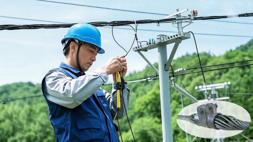
Essential hardware for OPGW installation includes tension and suspension clamps9 for securing cables, vibration dampers10 to reduce cable stress, and earth wires and accessories for proper grounding. These components ensure the cable system’s stability and reliability.
Hardware
Tension clamps are critical for fixing the cable on poles and towers, particularly at termination and corner towers. Ensure the clamp doesn’t exceed the side pressure intensity of the OPGW. Suspension clamps support the cable between towers, while vibration dampers help mitigate vibrations that could damage the cable. Additionally, install earth wires, downlead clamps, cable trays, and joint boxes according to design specifications.
I recall an anecdote from a project in Chile: The region had high winds year-round, and the local technicians initially did not install any vibration dampers. After a few months, microbending losses soared, and the fiber signal degraded. We installed Stockbridge-type dampers, and the cable stabilized. This saved them from more complex repairs.
Hardware Selection Criteria
-
Cable Diameter Compatibility:
- Each clamp or damper has a specific range of diameters.
- Using an ill-fitting clamp might pinch or slip on the cable.
-
Material Durability:
- Consider corrosion resistance.
- For coastal regions, use stainless steel or other rust-resistant metals.
-
Installation Environment:
- High-vibration areas need robust dampers.
- Steep terrain requires secure tension hardware to handle variable loads.
-
Local Standards:
- Some countries have codes or rules about clamp design and installation.
- Check for local certifications if required.
Table: Common Hardware and Their Functions
| Hardware | Primary Function | Typical Installation Point | Additional Note |
|---|---|---|---|
| Tension Clamp | Fixes cable at terminal or tension towers | Corner or dead-end towers | Must not crush or deform the OPGW |
| Suspension Clamp | Supports cable between towers | Straight-line towers | Allows free movement within specified range |
| Vibration Damper | Minimizes aeolian vibration | Spaced along span, near towers | Stockbridge dampers often used for overhead lines |
| Earth Wire & Accessories | Provides grounding | Tower earth point, ground rods | OPGW also acts as ground wire if designed that way |
| Downlead Clamp | Guides cable from top of tower to splice box | Tower body segments | Protects cable from abrasions along tower structure |
| Joint Box | Houses fiber splices | Tower-mounted or ground level | Protects splices from moisture, mechanical stress |
How Is Splicing and Testing Conducted for OPGW Cables?
Splicing and testing are the final steps that ensure the OPGW cables’ operational integrity and performance. This stage can be the deciding factor in whether your installation yields a stable, high-quality link or faces frequent network troubles. I have personally seen good installations ruined by sloppy splicing. People sometimes underestimate how critical it is to keep the splice environment clean, measure insertion loss, and track reflection.
Splicing
Utilize structure-mounted splice cabinet technology11. Prepare the cable ends and splice the fibers with precision to minimize splicing loss. Ensure the splice cases are sealed and protected adequately. I recall a project in a very dusty region of South Africa. We set up a temporary enclosure around the splice cabinet to keep out sand and dust. We also used an air compressor with a filter to blow away any debris before fusion splicing.
Best Practices for OPGW Splicing
-
Cleanliness:
- Use lint-free wipes and approved fiber cleaning solutions.
- Keep splicing tools sanitized to prevent dust buildup.
-
Proper Cleaving:
- Cleave the fiber at the recommended angle.
- Inspect cleaved ends under a microscope.
-
Fusion Splicing:
- Calibrate the fusion splicer for the specific fiber type.
- Perform a test splice on a scrap piece of fiber first.
-
Splice Case Management:
- Provide strain relief for fiber trays.
- Ensure watertight or moisture-proof closure.
-
Record-Keeping:
- Document the splice loss for each fiber.
- Maintain an updated cable layout with splice locations.
Testing
Conduct thorough testing to verify the optical performance and integrity of the installed OPGW cable. This step is crucial in ensuring the system’s reliability and identifying any potential issues early. In one large data center project I worked on in Mexico, we discovered an intermittent reflection event using an OTDR test. It turned out to be a subpar mechanical splice that was quickly replaced. Without that test, the network would have faced random outages.
Key Testing Methods
-
Optical Time Domain Reflectometer (OTDR):
- Locates potential breaks, splices, or high-loss events.
- Measures overall attenuation of the link.
-
Optical Insertion Loss (IL) Test:
- Uses a light source and power meter.
- Confirms if total link loss is within specifications.
-
Optical Return Loss (ORL) Test:
- Ensures minimal reflections.
- Important for high-speed data applications.
-
Visual Fault Locator (VFL):
- Red laser light to check for breaks or bending.
- Helps locate cable damage quickly in short distances.
Table: Recommended Test Parameters
| Test Type | Typical Equipment | Acceptable Range | Notes |
|---|---|---|---|
| Insertion Loss | Light Source & Power Meter | < 0.3 dB per splice (typical) | Varies by project, fiber type, and length |
| Return Loss | OTDR or RL Meter | > 40 dB recommended for single-mode | Higher values mean fewer reflections |
| OTDR Event | OTDR | – Analyze splices, detect breaks | Check for irregular spikes in the trace |
| Visual Fault Locator | VFL | – Not a quantitative test | Good for quick troubleshooting in the field |
What Are the Safety and Quality Control Measures for OPGW Installation?
Safety and quality control are non-negotiable elements of OPGW cable installation. Here’s how to implement them effectively. From my perspective, every site accident or cable failure is often rooted in a missed safety step. I once supervised a site where a worker almost fell from a tower because he wasn’t clipped to the safety harness properly. After that scare, we made sure daily safety checks were mandatory.
Maintain constant tension during the stringing process, ensure pulley conditions are optimal, and conduct regular quality checks12. These measures prevent damage and ensure the installation meets required standards.
Safety and Quality Control
Constant and controlled tension is vital during stringing to prevent sudden acceleration or deceleration that could damage the cable. Ensure pulleys are in good condition, well-lubricated, and grounded. Regular inspections during and after installation help identify any damage or defects, ensuring the installation meets necessary quality standards.
Safety Measures I Emphasize
-
Personal Protective Equipment (PPE):
- Hard hats, gloves, safety goggles, harnesses for tower work.
- Reflective vests and steel-toed shoes.
-
Risk Assessment:
- Walk the route to spot potential hazards like overhead obstacles or rocky terrain.
- Note weather changes, such as sudden storms.
-
Communication Protocols:
- Use radios or phones for real-time updates.
- Ensure everyone knows the hand signals if noise levels are high.
-
Grounding Procedures:
- Always ground your equipment to avoid accidental discharge.
- Check that no stray voltages are present in the tower or cable.
-
Emergency Plans:
- Have a rescue plan for tower-related incidents.
- Keep first-aid kits and trained personnel on-site.
Quality Control Essentials
-
Material Inspection:
- Inspect the cable drum for damage or signs of water infiltration.
- Validate cable length and verify batch numbers.
-
Installation Logs:
- Document tension readings, date, time, weather conditions.
- Take photos or videos of critical steps for reference.
-
Post-Installation Check:
- Inspect clamps, dampers, and splices for signs of stress or loosening.
- Conduct final OTDR or insertion loss tests.
-
Third-Party Audits:
- Invite external experts or authorized inspectors when required by local regulations.
- They can certify the cable route is installed per standards.
Table: Common Quality and Safety Checkpoints
| Checkpoint | Description | Frequency/Timing |
|---|---|---|
| Daily Tool Inspection | Verify tension machines, sheaves, grips | Start of each workday |
| Cable Drum Condition | Confirm no water infiltration or damage | Upon arrival and before stringing |
| Tension Calibration | Confirm dynamometer or tension gauge accuracy | Before major pulls or at shift changes |
| Safety Gear Inspection | Confirm harnesses, ropes, PPE in good shape | Start and end of each workday |
| Final Optical Tests | Validate splices, measure overall attenuation | End of installation, prior to handover |
Conclusion
In conclusion, successful OPGW cable installation hinges on meticulous pre-installation preparation, precise execution of the installation process, and rigorous splicing and testing. By adhering to these guidelines, telecom engineers and product managers can ensure their cable systems are reliable, durable, and efficient. As the backbone of telecommunications infrastructure, proper OPGW installation is not just a task but a critical component of network success.
I learned these lessons during my early days at ABPTEL when we saw a few installations fail because the teams overlooked certain small steps. Today, I see how the right combination of planning, training, tension control, and hardware choice can help big data centers and FTTA solutions remain stable. The same principle applies whether you are installing cables in a large metropolitan area or a remote wind farm. Every detail matters.
If you are considering an OPGW installation project, focus on the safety and quality checkpoints. Ensure the cable is tested properly. Train your crew to handle the unexpected. And remember that a carefully installed cable network can serve your business or organization for many years, providing reliable data and grounding support.
-
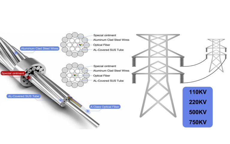
Optical Ground Wire (OPGW) is a type of cable used in telecommunications that combines the functions of grounding and fiber optic data transmission. ↩
-
Splicing and testing are critical stages in cable installation that ensure connections are secure and data transmission is efficient. ↩
-
Proper design and planning minimize errors and enhance the efficiency of the installation process by providing detailed guidance to the installation team. ↩
-
Staff training prepares the installation team by informing them about the equipment and procedures, ensuring a smooth and safe installation process. ↩
-
Adhering to safety protocols reduces the risk of accidents during cable installation and protects both workers and equipment. ↩
-
The tension pay-off method prevents cable sagging and ensures that the cable remains undamaged by obstacles or contact with the ground. ↩
-
Understanding the Rated Tensile Strength (RTS) is essential for maintaining the structural integrity of cables during tensioning and installation. ↩
-
Using appropriately sized sheaves helps to prevent cable bending and damage, ensuring smooth installation. ↩
-
Tension and suspension clamps are vital for securing cables along their route, especially at termination points and around corners. ↩
-
Vibration dampers are used to reduce mechanical stress caused by environmental factors like wind, thereby preserving the longevity of the cables. ↩
-
Structure-mounted splice cabinet technology allows for protected, precise splicing of fiber optics, reducing signal loss and maintaining system integrity. ↩
-
Regular quality checks help detect and rectify any potential faults in the cable installation, ensuring compliance with performance standards. ↩