2025 Data Center Architect’s Guide: How to Master 400G/800G Migration Pitfalls?
Hi, I’m Candy from ABPTEL.
In the 10G era, you could be sloppy and still get link. At 400G and 800G, physics is strict. A channel lives or dies on loss budget, polarity, and cleanliness.
400G/800G succeeds when you control channel loss and polarity. Use low-loss MTP® Elite connectors, verify Type-B for parallel optics, and keep end-faces clean. With multi-pair links, design ≤0.35 dB per mated pair to protect margin; wrong gender or dust will kill the link.
We use the checklist below with operators and cloud teams. It turns “Link Down” into “Green” without guesswork.
Why does the optical link budget collapse in 400G/800G?
Spine–leaf links often include 4–6 MPO/MTP mated pairs. On 400G, a “standard-loss” design can burn your entire budget before you account for fiber attenuation.
Use low-loss MTP® Elite ferrules. They keep per-pair loss around 0.35 dB and create the margin you need for parallel optics and tight lanes.

PHY cheat-sheet (design targets)
| 400G PHY | Media | Typical reach | Channel loss (design target) | Notes |
|---|---|---|---|---|
| SR8 | OM4/OM5 (MPO-12) | 100–150 m | ≤ ~1.5–2.0 dB | 8 lanes parallel; Type-B polarity common |
| DR4 | OS2 (MPO-12/MPO-8) | up to 500 m | ≤ ~3.0 dB | 4 lanes PAM4 each way |
| FR4 | OS2 (LC duplex) | up to 2 km | ≤ ~3.0 dB | CWDM4 over 2 fibers |
| LR4 | OS2 (LC duplex) | up to 10 km | ≤ ~3.0 dB | Long leaf–spine or campus |
Always confirm the exact Tx/Rx spec in the module datasheet. The table above is conservative for design.
Decision checklist
- Mated pairs: Count all MPO mates end-to-end. If ≥5, low-loss ferrules are mandatory.
- Fiber type and reach: OM4 to 100 m; OM5 for 100–150 m or SWDM. OS2 for DR4/FR4/LR4.
- Module margin: Compare Tx min to Rx sensitivity. Tight margin demands low-loss hardware.
- Testing plan: Budget time for IL/RL tests and end-face inspection on day one.
Standard vs low-loss comparison
| Factor | “Standard” MPO design | ABPTEL low-loss design | Notes |
|---|---|---|---|
| Max loss per mate | 0.75 dB | 0.35 dB | Typical measured <0.30 dB |
| Total loss (4 mates) | 3.00 dB | 1.40 dB | Connectors only |
| 400G DR4 headroom | 0 dB (risky) | ~1.6 dB (safe) | Leaves margin for dust/aging |
| Best use | Legacy 10G/40G | 400G/800G | High-density DC |
Worked examples you can copy
A) 400G SR8 over OM4, 90 m, 4 mates (low-loss)
Connectors: 4 × 0.35 dB = 1.40 dB
Fiber: 0.09 km × 3.0 dB/km = 0.27 dB
Total ≈ 1.67 dB → within SR8 design target with good margin.
B) 400G DR4 over OS2, 300 m, 6 mates (low-loss)
Connectors: 6 × 0.35 dB = 2.10 dB
Fiber: 0.30 km × 0.35 dB/km = 0.11 dB
Total ≈ 2.21 dB → leaves usable headroom vs typical DR4 target.
Rule of thumb: if mated pairs ≥5, low-loss is not optional.
How do I troubleshoot MPO/MTP gender and polarity like a pro?
Most “bad cable” tickets are not quality issues. They are gender or polarity mistakes.
Gender basics
- Male (pinned): two guide pins at the ferrule.
- Female (unpinned): two holes, no pins.
- Rule: transceivers are typically Male. The patch cord that plugs into a transceiver must be Female.
Never mate Male ↔ Male (pin damage) or Female ↔ Female (no alignment → no light).
Polarity quick map
| Scenario | Gender | Polarity | Why |
|---|---|---|---|
| QSFP-DD ↔ QSFP-DD (SR8) | Transceivers Male → patch Female | Type-B | Reverses 1↔12, 2↔11 … aligns Tx/Rx lanes |
| QSFP-DD DR4 → 4×100G breakout | Factory-mapped harness | As-built | Follow harness P/N mapping; do not flip lanes in the field |
Common traps
- Mixing Type-A and Type-B across trunks and cassettes.
- Using a pinned patch on a pinned transceiver.
- Forgetting that some DR4→LC/CS harnesses have specific lane orders from the factory.
Fast fix
- Check gender at every port.
- Confirm Type-B for SR8 direct links; confirm harness mapping for DR4 breakouts.
- If in doubt, test with a polarity mapper before turn-up.
What components form a robust 400G ecosystem?
A chain is only as strong as the weakest link. Use a verified set from backbone to patch.
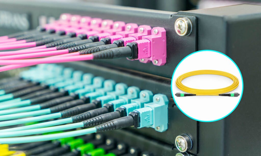
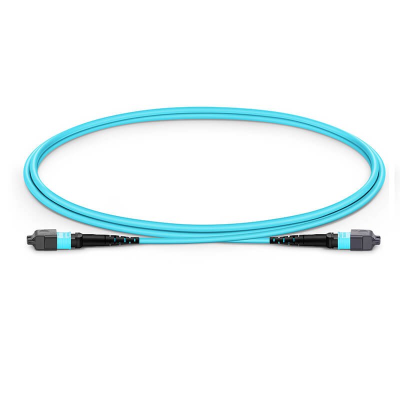
1) Backbone: MPO/MTP trunk cables
- Low-loss MTP® Elite ferrules, 12F/24F/144F options.
- Reel-in-box packaging to protect ferrules during pulls.
- Label each leg for polarity.
- See MPO/MTP Trunk Cables .
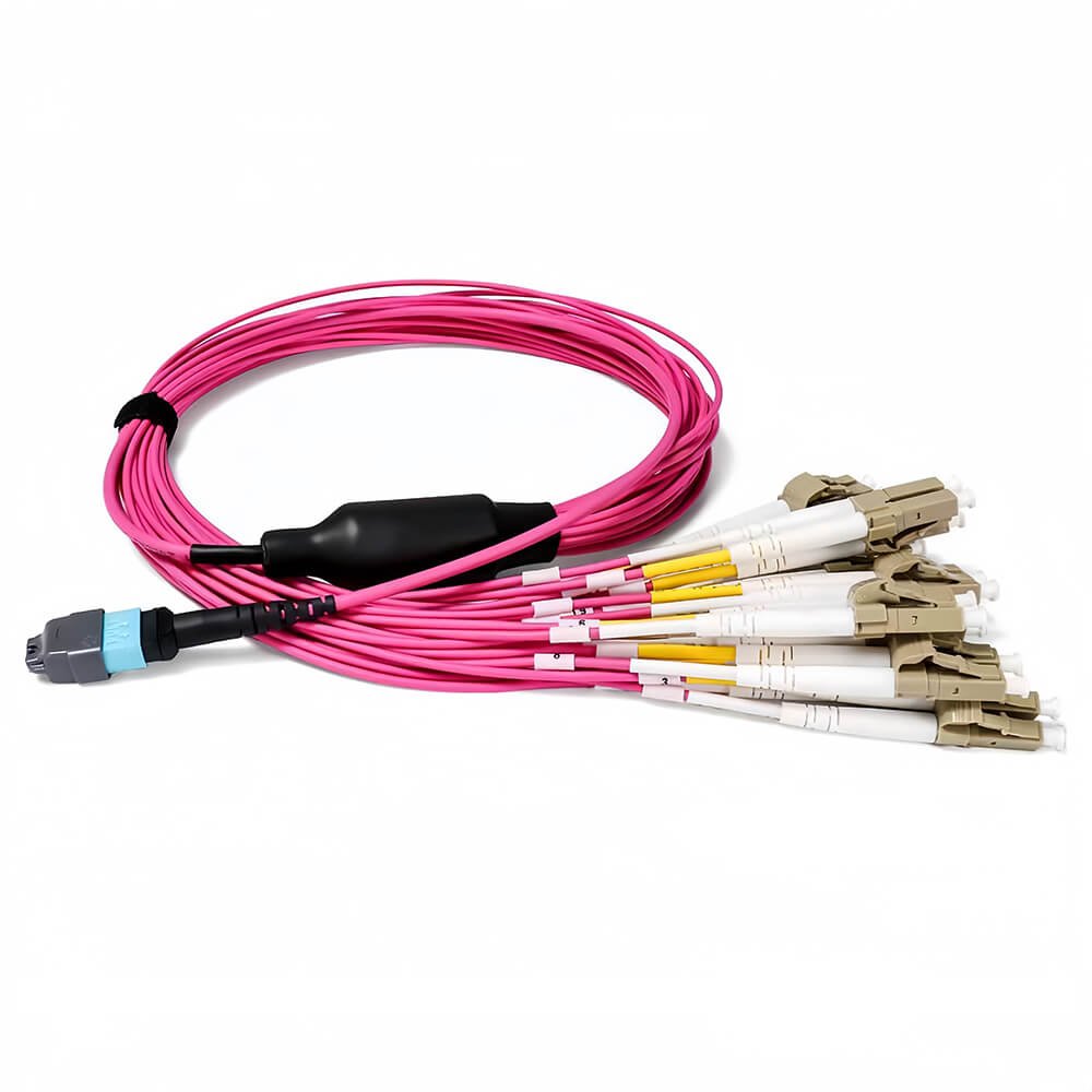
2) Distribution: MPO/MTP fanout (breakout) cables
- Break a 400G port into 4×100G or 8×50G.
- Uniboot LC/CS on the server side to cut bulk and improve airflow.
- See MPO/MTP Fanout Cables.
3) Density: cassettes and patch panels
- 1U panel with 12 cassettes yields up to 144 LC ports.
- Manageable patching and clean RU usage in hot aisles.
- See High-Density Cassettes & Panels
4) Cleanliness: inspection and cleaning tools
- Inspect to IEC 61300-3-35, clean with one-click MPO tools, re-inspect.
- Add cleaners to every turn-up kit.
- See MPO One-Click Cleaner.
Turn-up checklist (6 steps)
- Inspect MPO/MTP end-faces (IEC 61300-3-35).
- Clean with MPO one-click; re-inspect.
- Test IL/RL per TIA-568.3-D with reference jumpers; save results.
- Verify polarity with a mapper.
- Validate mapping for DR4 breakouts in a pilot rack.
- Enable FEC and watch counters after burn-in.
Conclusion
Pick the safe path:
- Budget first: Design ≤0.35 dB per mate. Use MTP® Elite across trunks, cassettes, and patch cords.
- Check polarity: Use Type-B for SR8; follow harness mapping for DR4; never pin-to-pin.
- Cleanliness is king: Inspect-clean-inspect every time.
Start with one pilot row: measure IL/RL, confirm polarity, and record a clean runbook your team can reuse.
FAQ
Q1. What is a safe connector loss target for 400G/800G?
A1. Design for ≤0.35 dB per mated pair with MTP® Elite ferrules. This preserves margin for SR8/DR4 and protects against dust and handling.
Q2. How do I avoid gender mistakes on site?
A2. Remember: transceivers are usually Male; the patch into a transceiver must be Female. Never Male-to-Male or Female-to-Female.
Q3. OM4 or OM5 for short-reach 400G?
A3. OM4 is efficient to ~100 m. Use OM5 for 100–150 m or SWDM/BiDi strategies. For 500 m, move to OS2 with DR4/FR4.
Q4. What 1U density can I expect with cassettes?
A4. A 1U frame with 12 LC cassettes supports up to 144 LC ports, keeping airflow and serviceability under control.
Want a neutral BOM review or vendor-coding check?
Candy@abptel.com · WhatsApp +86-188-1445-5697
ABPTEL validates polarity, IL budgets, and QSFP-DD mappings and provides pilot samples with IL/RL reports.